
Elevator balance weight

A technology of elevators and counterweights, which is applied to elevators in buildings, elevators, and lifting equipment in mines, etc. It can solve the problems of wasting installation space, increasing the types of components, and extending the length of parts, so as to save space and achieve flexibility Effect

Inactive Publication Date: 2004-05-26
INVENTIO AG
View PDF1 Cites 10 Cited by
  • Summary
  • Abstract
  • Description
  • Claims
  • Application Information

AI Technical Summary

Problems solved by technology

In addition, a large part of the elevator counterweight installation space is lost because the lower extension of the vertical frame profile, which is used to fix the guide shoe and the safety brake device, cannot be used as the installation space for the weight
[0009] In elevator installations without a safety brake on the counterweight, either the lower extension is too long, wasting installation space, or a different extension is required, increasing the variety of components and increasing errors. risk of delivery

Method used


Image

  • Elevator balance weight
  • Elevator balance weight
  • Elevator balance weight

Examples


Embodiment Construction

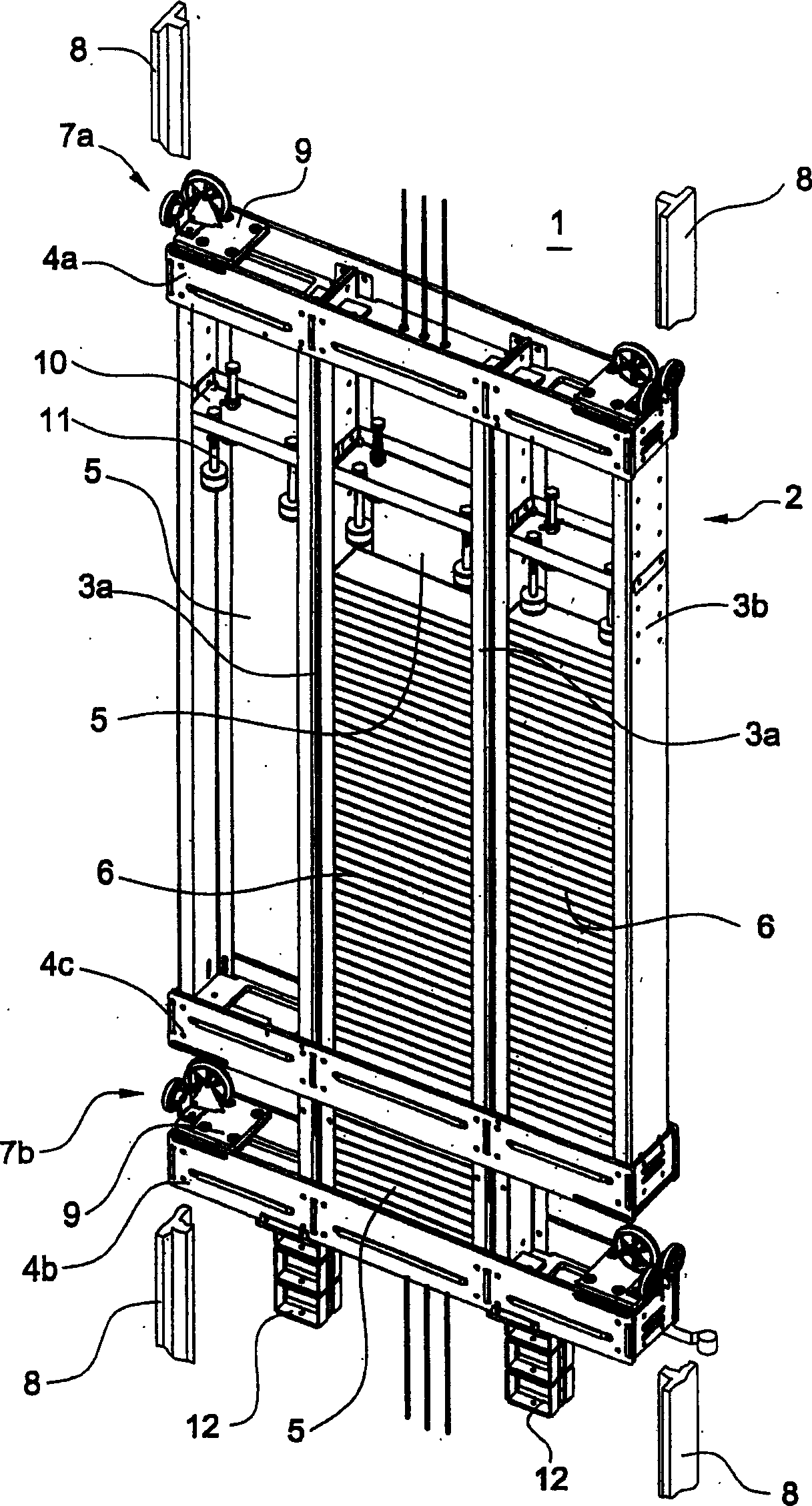
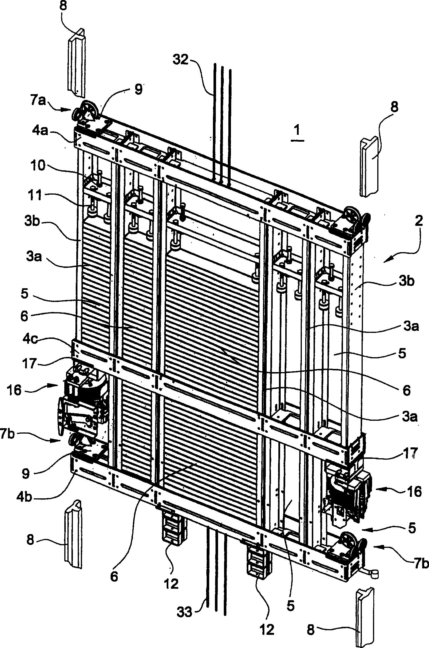
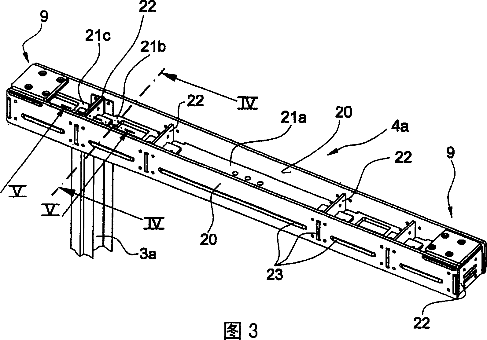
[0032] figure 1 A first embodiment of an elevator counterweight 1 according to the invention is shown, said elevator counterweight 1 having a counterweight frame 2 with four vertical beams 3a, 3b, an uppermost horizontal beam 4a, A lowermost horizontal beam 4b, and a second lowermost horizontal beam 4c. The middle vertical beams 3 a each have two U-shaped profiles arranged in pairs, while each outermost vertical beam 3 b is formed from a corresponding single U-shaped profile. The vertical beams 3 a , 3 b and the horizontal beams 4 a , 4 b , 4 c together form a grid-shaped counterweight frame with a plurality of grid areas 5 for receiving weights 6 . The horizontal beams 4a, 4b, 4c are designed such that the vertical beams 3a, 3b can penetrate said horizontal beams at predetermined scarf points, wherein the horizontal beams and the vertical beams are in each case connected together at the scarf points.

[0033] The vertical beams 3a, 3b, arranged in pairs and individually, ar...


PUM


Abstract

An elevator counterweight (1) comprises a counterweight frame (2) which is constructed of several vertical beams (3a, 3b) and at least three horizontal crossbars (4a, 4b, 4c), which are arranged in the same plane. The vertical beams (3a, 3b) penetrate the horizontal crossbars (4a, 4b, 4c) and form therewith several grid fields in which weight elements (6) are arranged and fixed. The two outermost grid fields disposed above the lowermost horizontal crossbar (4b) are open towards the side, and each can receive a respective counterweight guide shoe or a lower counterweight guide shoe (7b) and the safety brake device (16).

Description

technical field [0001] The invention relates to an elevator counterweight. The elevator counterweight includes a counterweight frame and weight parts fixed in the counterweight frame, and the counterweight is connected with the elevator car by a flexible bearing device, thereby realizing the elevator counterweight and the elevator car. The direction of movement of the box is reversed along the movement of the counterweight guide rail. Background technique [0002] On the one hand, the elevator counterweight is intended to load, at the end that is not fixed to the elevator car, the carrier that drives the elevator car, so that the driving wheel of the elevator drive surrounding the carrier transfers the necessary frictional forces to the carrier. On the other hand, the task of the counterweight is to compensate for the part of the total load which is moved by the elevator drive and consists of the weight of the elevator car and the payload, so that the required drive power ca...

Claims


Application Information

Patent Timeline
Patent Type & Authority Applications(China)
IPC IPC(8): B66B11/00B66B17/12
CPCB66B17/12
Inventor 达利奥·奥古格里亚洛
Owner INVENTIO AG
Learn More