
Touch panel for liquid crystal disply device

A touch panel and substrate technology, which is applied in the input/output process of data processing, the input/output of user/computer interaction, optics, etc., and can solve the problems of worn touch panels, difficult writing, and difficult tracking of stylus contacts.

Inactive Publication Date: 2004-06-02
LG PHILIPS LCD CO LTD
View PDF0 Cites 1 Cited by
  • Summary
  • Abstract
  • Description
  • Claims
  • Application Information

AI Technical Summary

Problems solved by technology

However, it is difficult to write on such touchpads integrated into the LCD panel because the contact point of the stylus (or finger) is not easy to track unless the user depresses the entire stroke of the stylus firmly during the writing process.
Having to press hard for the entire time of writing causes user fatigue
Additionally, the user wears down the touchpad more quickly due to pressing harder on the touchpad

Method used


Image

  • Touch panel for liquid crystal disply device
  • Touch panel for liquid crystal disply device
  • Touch panel for liquid crystal disply device

Examples


Embodiment Construction

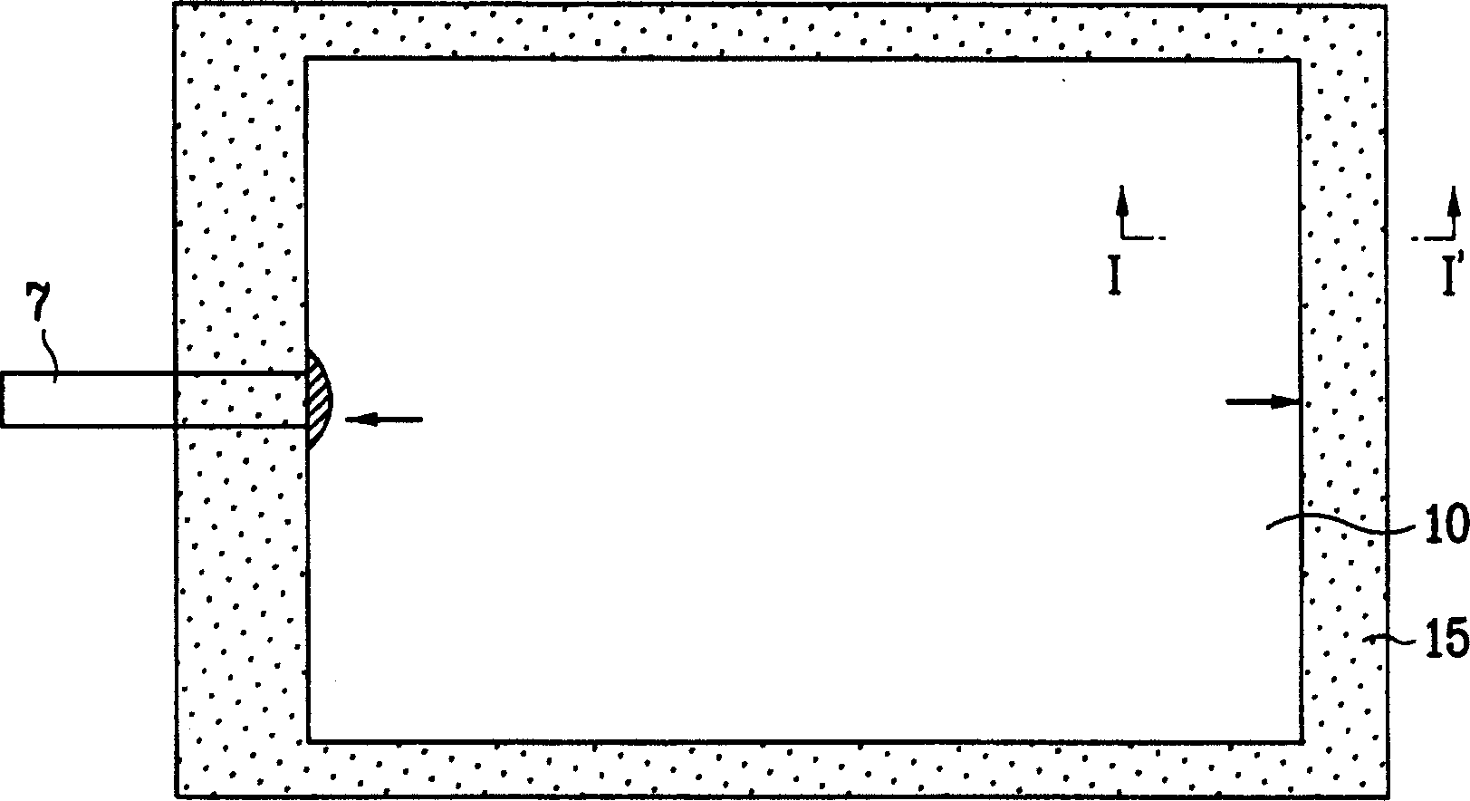
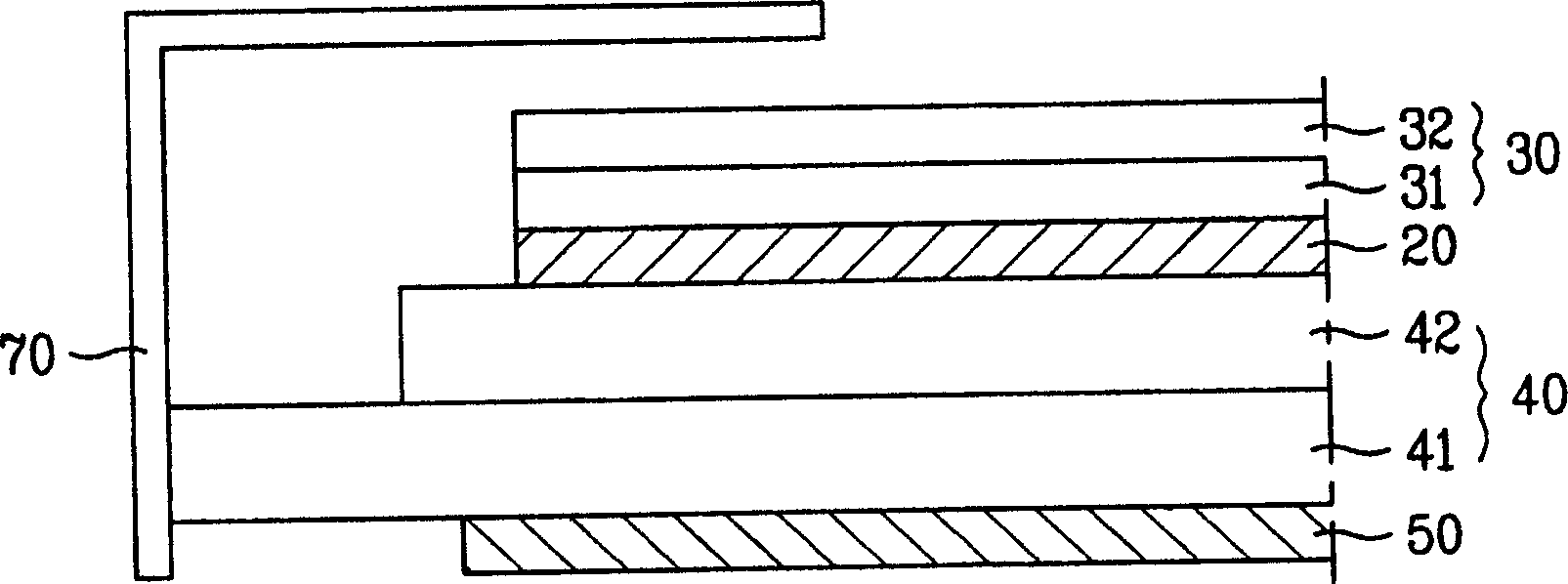
[0028] Embodiments of the present invention will now be explained in detail, specific examples of which are given in the accompanying drawings. Wherever possible, the same reference numbers will be used throughout the drawings to refer to the same or like parts. The present inventors have found that forming the hard paint layer by spraying particles or forming an anti-glare layer having a plurality of relief patterns thereon increases the need for the user to have to depress the touch panel harder. More specifically, the anti-glare layer affects the detection of the touch of the stylus (or finger) as it moves across the touchpad. Hereinafter, a touch panel integrated with an LCD device according to a preferred embodiment of the present invention will be described with reference to the accompanying drawings.

[0029] Figure 7 is a method for bonding the touch panel and the polarizing plate in the touch panel integrated with the LCD device according to an embodiment of the pr...


PUM

PropertyMeasurementUnit
thicknessaaaaaaaaaa
thicknessaaaaaaaaaa

Abstract

A touch panel integrated with an LCD device includes a lower polarizing plate, an LCD panel having a lower substrate on the lower polarizing plate, an upper substrate on the lower substrate, and a liquid crystal layer between the upper and lower substrates, an upper polarizing plate on the upper substrate having a planar surface and a touch panel bonded directly to the planar surface of the upper polarizing plate.

Description

[0001] This application claims the benefit of Korean Patent Application No. P2002-71188 filed in Korea on Nov. 15, 2002, the entire contents of which are incorporated herein by reference. technical field [0002] The present invention relates to a touch panel, and more particularly, to a touch panel of an LCD device for obtaining comfortable writing feeling and durability by improving an upper polarizing plate of a touch panel-integrated LCD panel. Background technique [0003] In personal information processors, such as personal computers or mobile transmission devices, various input devices such as keyboards, mice and digitizers have generally been used to input text and graphics. As personal computers are being developed for use in various fields, since both flexibility and simplicity are required, it has been required to use a touch panel instead of a keyboard and a mouse. For example, the user can input information such as letters on the touch panel while holding the to...

Claims


Application Information

Patent Timeline
Patent Type & Authority Applications(China)
IPC IPC(8): G06F3/03G06F3/033G06F3/041
CPCG06F3/0412G06F3/045G06F3/03
Inventor 方龙翼朴喜正
Owner LG PHILIPS LCD CO LTD
Learn More