Ophthalmologic apparatus

An eye detection and eye technology, used in eye testing equipment, comprehensive refractometers, medical science, etc., can solve problems such as damage to the reliability of eye detection, prolonged eye detection, and difficulty in identification.

Inactive Publication Date: 2004-06-16
KK TOPCON
View PDF1 Cites 5 Cited by
  • Summary
  • Abstract
  • Description
  • Claims
  • Application Information

AI Technical Summary

Problems solved by technology

For example, when a plurality of optotypes are presented to the detected eyes or the state of the optotype presentation (the state of the optotype images projected onto the detected eyes), the visual recognition of multiple optotypes is compared and judged subjectively by the subject to be tested. In the inspection of the test, it is difficult for the examinee to identify which of the multiple optotypes is being prompted
As an example, in the general method of astigmatism examination, that is, the cross cylinder test (hereinafter referred to as CC test), according to the comparison and judgment of the subject, it can be clearly seen that a pair of positive and negative optical powers of the cross cylinder is reversed. Which one of the visual mark prompts the state is checked, but at this time, it often happens that the person being tested cannot tell which is which visual mark prompts the state, which not only causes the long-term eye detection, but also becomes a damage to the eye detection a cause of reliability
[0005] In addition, even in the CC test when the inspector or assistant is present, it is also difficult for the inspected to successfully select the state of the visual mark prompt

Method used


Image

  • Ophthalmologic apparatus
  • Ophthalmologic apparatus
  • Ophthalmologic apparatus

Examples


Embodiment 1

[0034] [the whole frame]

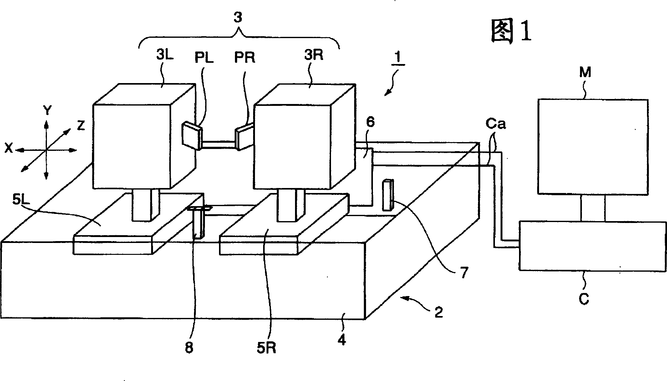
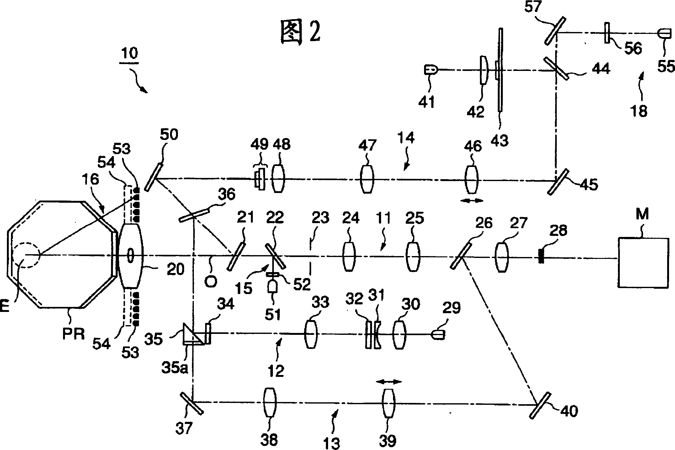
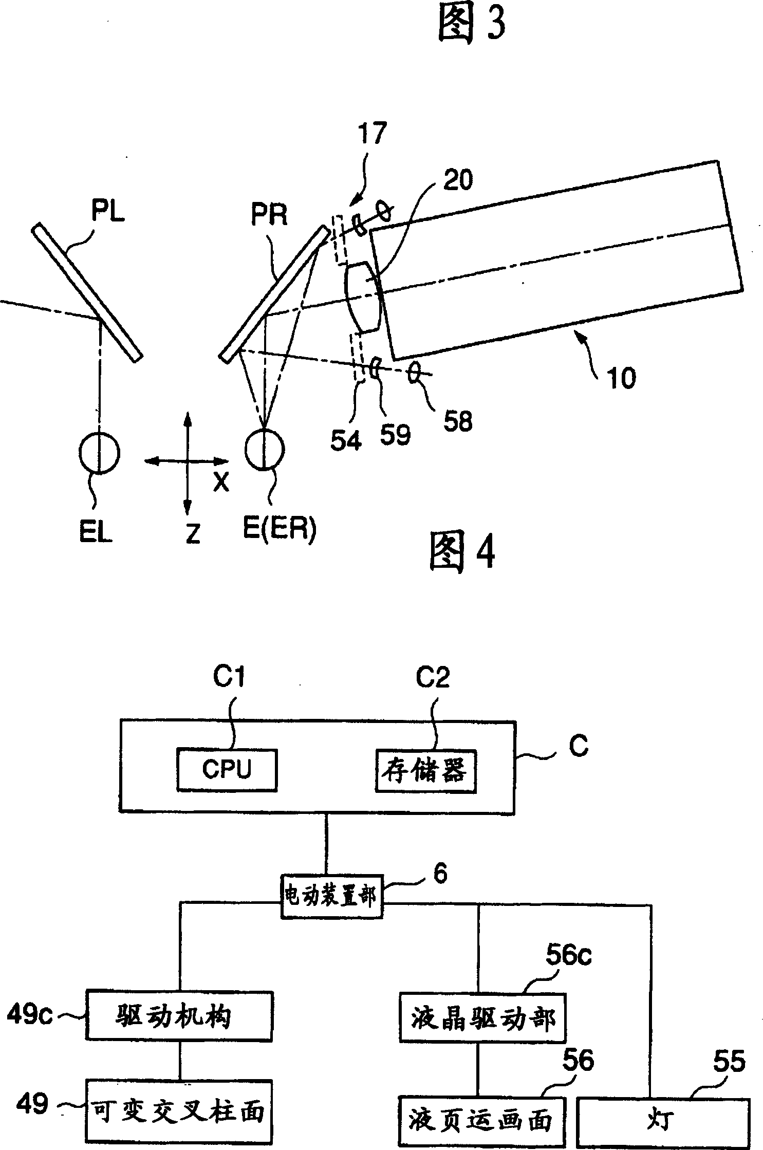
[0035] FIG. 1 is a perspective view showing an outline of the overall configuration of an eye detection device 1 according to Embodiment 1. As shown in FIG. The eye testing device 1 is a device capable of performing astigmatism testing in addition to self-perceived power measurement and other-perceived power measurement alone or in connection with assistants guiding multiple subjects. The eye detection based on the eye detection device 1 is automatically carried out along the given steps. First, the approximate value of the refractive power of the detected eye E is obtained through the measurement of the power of the other person's perception method, and the measurement of the power of the self-perception method is performed based on the approximate value. For measurement, after the astigmatism power is obtained by the astigmatism test, the spherical power is adjusted, and the visual acuity test is performed with the last obtained power. It should b...

Embodiment 2

[0085] Below, refer to Figure 11 Embodiment 2 of the present invention will be described. Figure 11 An identifier display member 60 is shown instead of the liquid crystal screen 56 of the eye detection device 1 . Figure 11 (a) is a perspective view showing a schematic structure when viewing the identifier display member 60 from the front, Figure 11 (b) is a side view showing a schematic structure of the identifier display member 60 . It should be pointed out that in Figure 11 (b) shows a state where the liquid crystal screen 56 of the eye detection device 1 is replaced by the identifier display member 60, and the lamp 55 and the identifier display member 60 constitute identification information generating means.

[0086] As shown in the two figures, the identifier display member 60 includes: an identification target plate 61 for displaying an identifier “1” 61a and an identifier “2” 61b; and a shutter 62 for covering a part of the identification target plate 61 . The ...

Embodiment 3

[0092] The purpose of Embodiment 3 of the present invention described below is to improve the ability to recognize an optotype by simultaneously projecting a colored fusion frame and an optotype. The fusion frame is an optotype for promoting the fusion of the respectively recognized optotype images from the left eye EL and right eye ER when eye detection is performed by simultaneously projecting optotypes to both eyes of the subject. It should be noted that this embodiment has almost the same structure as the above-mentioned Embodiment 1, so only its characteristic part (identifier generating optical system) will be described.

[0093] As described above, the identifier generating optical system 18 is built in each of the left-eye head 3L and the right-eye head 3R. In this embodiment, as the lamp 55 of the identifier generating optical system 18, for example, a multi-color LED that switches between red light and green light is arranged. The switching operation by this multico...


PUM


Abstract

Provided is an optometer solving confusion of a subject by improving the discrimination of an indicator and an indicator presenting state and shortening the optometry time and improving the reliability of the optometry.This optometer 1 includes an indicator plate 43 displaying the indicator S, an indicator projecting optical system 14 projecting the indicator S on an examined eye E, a variable cross cylinder 49 generating a pair of indicator presenting states of the indicator S used for a cross cylinder test, a lamp 55 and a liquid crystal screen 56 generating identifiers 56a1 and 56b1 as identification information, and a dichroic mirror 44 for synthesizing the identifiers 56a1 and 56b1 into the pair of indicator presenting states respectively and presenting them to the examined eye E.

Description

technical field [0001] The present invention relates to an eye testing device capable of measuring at least the optical power of an eye to be tested in a perceptual manner. Background technique [0002] In the measurement of the optical power (eye optical power) of the subject's eye, eye detection based on the self-perceived method measured based on the response of the subject to Landrutto's ring and other visual targets has been used at the same time. Eye detection of the way others perceive (the way others can feel or see) in response to the tester's response. Currently, eye testing devices that can effectively utilize both the self-sensing and other-sensing methods of eye testing are widespread, and efficiency and reliability of inspections have been improved, and space-saving devices have been sought. [0003] In addition, in order to improve the efficiency of inspections, we have developed an eye inspection device in which the subject can perform eye inspections by him...

Claims


Application Information

Patent Timeline
Patent Type & Authority Applications(China)
IPC IPC(8): A61B3/028A61B3/032A61B3/036A61B3/15
CPCA61B3/0325A61B3/036A61B3/152A61B3/032A61B3/028
Inventor 林健史
Owner KK TOPCON
Why Eureka
Try Eureka