Method for producing a wiring harness and an apparatus for connecting a terminal-connected wire

A manufacturing method and a technology of a connecting device, which are applied in the manufacturing field of harnesses, can solve the problems such as the inability to increase the utilization rate of modules and the increase of equipment costs.

Inactive Publication Date: 2004-06-16
SUMITOMO WIRING SYST LTD
View PDF3 Cites 14 Cited by
  • Summary
  • Abstract
  • Description
  • Claims
  • Application Information

AI Technical Summary

Problems solved by technology

As a result, equipment costs continue to increase, but the utilization rate of each module cannot be increased

Method used


Image

  • Method for producing a wiring harness and an apparatus for connecting a terminal-connected wire
  • Method for producing a wiring harness and an apparatus for connecting a terminal-connected wire
  • Method for producing a wiring harness and an apparatus for connecting a terminal-connected wire

Examples


Embodiment Construction

[0035] Hereinafter, embodiments of the present invention will be described with reference to the drawings.

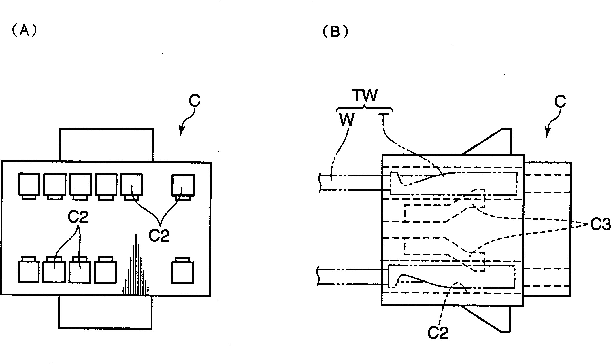
[0036] figure 1 It is a schematic external view of the connection box (Connect housing) which concerns on this embodiment, (A) is a front view, (B) is a side view.

[0037] refer to figure 1(A)(B), the connection box C in the figure, forms a plurality of holes (Cavity) C2 distributed asymmetrically on its front. The holes C2 are arranged in two rows up and down when viewed from the front, and the phases of the terminals T of the terminal wires TW are reversed at the positions of the upper row and the lower row. A cantilever-shaped locking tongue (locking tongue) C3 is provided in each hole C2. The brake reed C3 adopts a common brake method, and fits into the groove formed on the bottom surface of the terminal T, so that the terminal T is fixed in the connection box C. In the illustrated embodiment, each brake reed C3 has a free end extending upward from the bottom...


PUM


Abstract

A method for manufacturing a wire harness comprises an electric wire mixed flow process of supplying a plurality of the electric wires with terminals TWs with different specifications on the same line; an electric wire holding process of holding terminals Ts of the supplied wires TWs in a manner that the terminals Ts can perform the inserting operations by at least a chuck for a terminal 208; an inserting means selecting process of selecting a suitable one among a plurality of terminal inserting means 230, 240 to insert terminals Ts in an inserting process in response to the kinds of supplied wires TWs. The inserting process is performed in cooperation the inserting means 230, 240 selected in the selecting process with the chuck 208.

Description

technical field [0001] The invention relates to a manufacturing method of a wire harness and a terminal-connected wire connection device. Background technique [0002] Generally, a connecting process in which electric wires are connected to connectors is necessary when manufacturing a harness. As a specific device for the above-mentioned connection process, an insertion manipulator that inserts a terminal wire with a terminal wire connected to the end of the connector into the connection box of the connector is generally used. Japanese Patent No. 3019737 (pages 2 to 3, figure 2 ) has been made public. [0003] Most of the above-mentioned devices include a terminal chuck for guiding the terminal of the terminal-equipped wire and a wire clamp for clamping the covered part of the terminal-equipped wire near the terminal chuck, and the device accommodates the terminal positioned by the terminal chuck facing the terminal of the connection box. chamb...

Claims


Application Information

Patent Timeline
Patent Type & Authority Applications(China)
IPC IPC(8): H01B13/012H01R43/20
CPCY10T29/53213H01R43/20Y10T29/5142Y10T29/49222Y10T29/49174Y10T29/5193Y10T29/5138Y10T29/53235
Inventor 白川纯一葛山智视深田一光
Owner SUMITOMO WIRING SYST LTD
Why Eureka
Try Eureka