Tyre evenness tester

A uniformity and testing machine technology, which is applied in the direction of automobile tire testing, tire installation, tire parts, etc., can solve the problems of reduced speed, narrowed gap, and adverse effects on measurement accuracy.

Inactive Publication Date: 2004-07-07
KOBE STEEL LTD
View PDF3 Cites 20 Cited by
  • Summary
  • Abstract
  • Description
  • Claims
  • Application Information

AI Technical Summary

Problems solved by technology

However, since the lock shaft is inserted into the mandrel, there is an unavoidable gap between the two. Therefore, there is a problem that the measurement accuracy is adversely affected due to eccentricity.
For this problem, the gap can be reduced as much as possible, but due to the limitation of machining accuracy and assembly accuracy, it is impossible to reduce the gap enough to prevent eccentricity
Furthermore, in the structure of No. 11-223571, before inserting the lock shaft into the mandrel, in order not to cause damage when the two come into contact, the speed must be sufficiently reduced, and there is a problem that the cycle time is long.

Method used


Image

  • Tyre evenness tester
  • Tyre evenness tester
  • Tyre evenness tester

Examples


Embodiment Construction

[0044] Below according to Figure 1 to Figure 8 Embodiments of the present invention will be described.

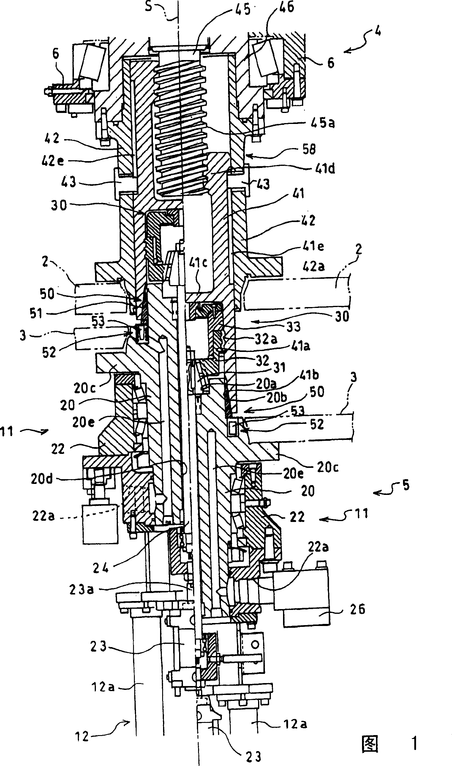
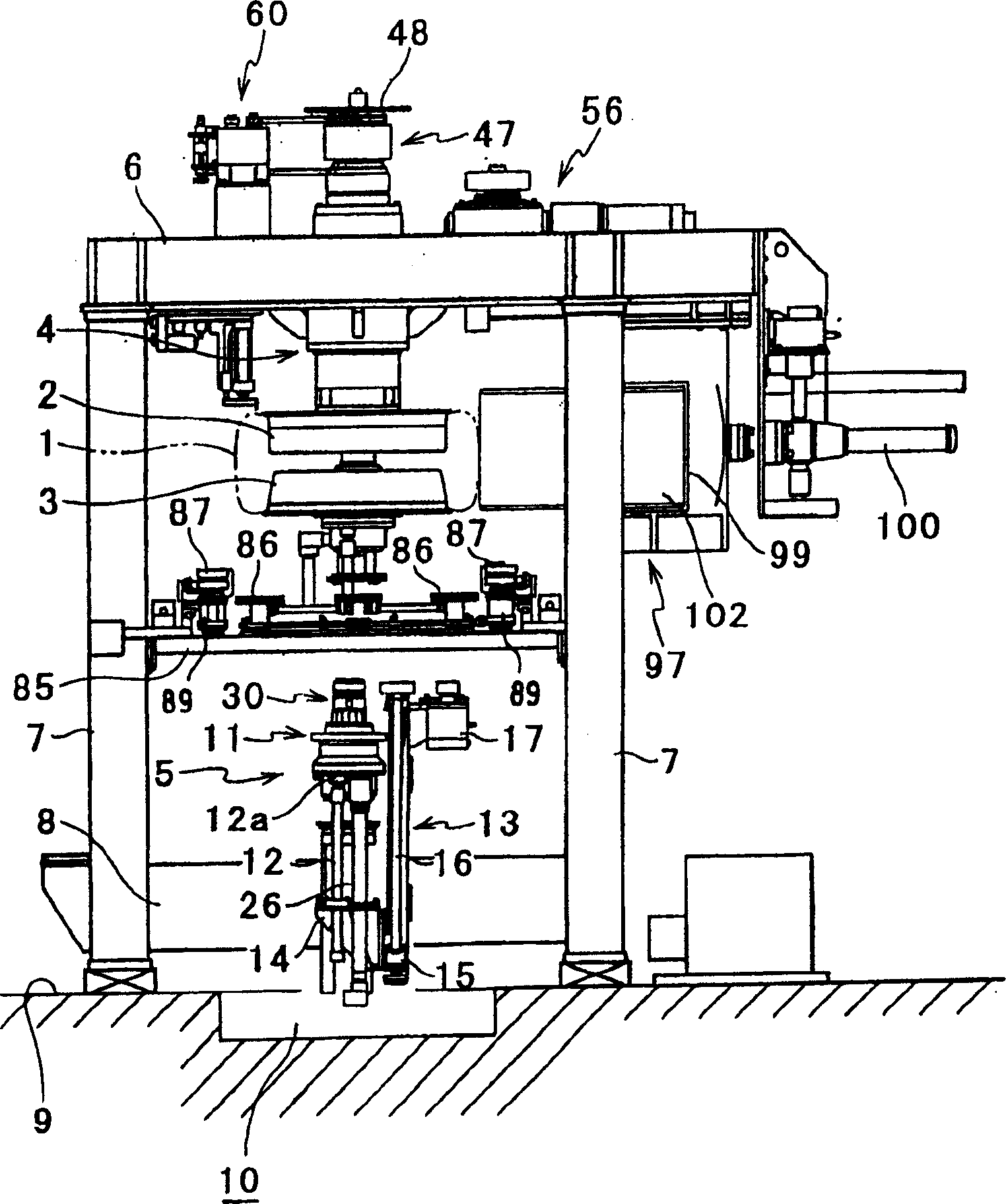
[0045] According to the tire uniformity testing machine of the present embodiment, such as figure 2 As shown, the upper rim 2 holding the upper bead portion of the tire 1 and the lower rim 3 holding the lower bead portion of the tire 1 are included. The upper rim 2 is detachably provided on the front end portion (lower end portion) of the upper spindle 4 . On the other hand, the lower rim 3 is detachably provided on the front end portion (upper end portion) of the lower spindle 5 . The two mandrels 4, 5 make the upper rim 2 and the lower rim 3 face each other, and at the same time, make the axes of the two rims 2, 3 be on the same straight line and coincide with each other.

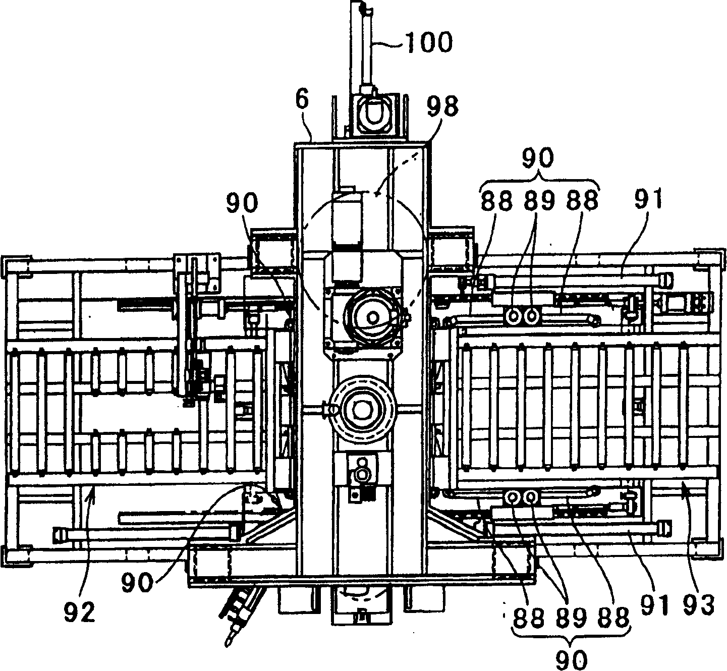
[0046] The upper mandrel 4 and the lower mandrel 5 are respectively arranged on the top frame 6 and the bottom frame 8 . These racks 6 and 8 are supported by a plurality of racks 7 arranged vertic...


PUM


Abstract

A tire uniformity machine is provided to prevent axes of rims from being misaligned while shortening a measurement cycle by installing a rim width adjustment unit in a first spindle. A tire uniformity machine includes an upper rim(2) for supporting and holding an upper bead section of a tire(1) and a lower rim(3) for supporting and holding a lower bead section of the tire(1). The upper rim(2) is detachably attached to a lower end of an upper spindle(5). The upper rim(2) is oppositely aligned with respect to the lower rim(3) by means of lower and upper spindles(4,5) in such a manner that axes of the upper and lower rims(2,3) are aligned in the same line. The lower and upper spindles(4,5) are installed on a top frame(6) and a base frame(8), respectively. The top and base frames(6,8) are supported by an installation frame(7).

Description

technical field [0001] The present invention relates to a tire uniformity testing machine for inspecting tire uniformity by rotating the tire while supplying compressed air. Background technique [0002] In general, a tire uniformity testing machine clamps the upper and lower bead portions of the tire from both sides with the upper and lower rims respectively, and then supplies compressed air into the tire to check the uniformity of the tire when the tire is rotated together with the upper and lower rims. At the same time, the tire uniformity testing machine constituted in this way, in order to adapt to the form of multi-variety and small-scale production of tires with various bead widths produced in the same factory, it is hoped that tires with various bead widths can be inspected on one device. . [0003] Therefore, in the prior art, the proposal of the following structure is proposed, that is, under the lower spindle on which the lower rim is mounted concentrically, an i...

Claims


Application Information

Patent Timeline
Patent Type & Authority Applications(China)
IPC IPC(8): G01M17/02
CPCB60C25/002G01M1/045G01M17/021
Inventor 车地正信住谷敬志柳原敏男加藤干雄野中俊克
Owner KOBE STEEL LTD
Why Eureka
Try Eureka