Shutter device

A technology of shutters and blades, which is applied in the structural field of shutter devices, and can solve the problems of increasing blade space and unfavorable miniaturization of shutter devices.

Inactive Publication Date: 2004-07-14
OLYMPUS CORP
View PDF2 Cites 8 Cited by
  • Summary
  • Abstract
  • Description
  • Claims
  • Application Information

AI Technical Summary

Problems solved by technology

In this case, the relative positional relationship between the above-mentioned elastic buffer member and the above-mentioned shutter opening plate and shutter closing plate also has a great influence on the rebound effect, so it is also difficult to expect the specified effect of preventing rebound.
[0008] In addition, in the various devices disclosed in the above-mentioned Japanese Patent Application Publication No. 9-5831, the above-mentioned Patent Publication No. 2627904, and the above-mentioned Publication No. 62-3792, in order to arrange the above-mentioned elastic buffer member to be connected to the blade and the shutter plate member Relatively, it is necessary to increase the space in the direction of movement of the blades near the terminal position, which is disadvantageous for the miniaturization of the shutter device.

Method used


Image

  • Shutter device
  • Shutter device
  • Shutter device

Examples


Embodiment Construction

[0025] Embodiments of the present invention will be described below with reference to the drawings.

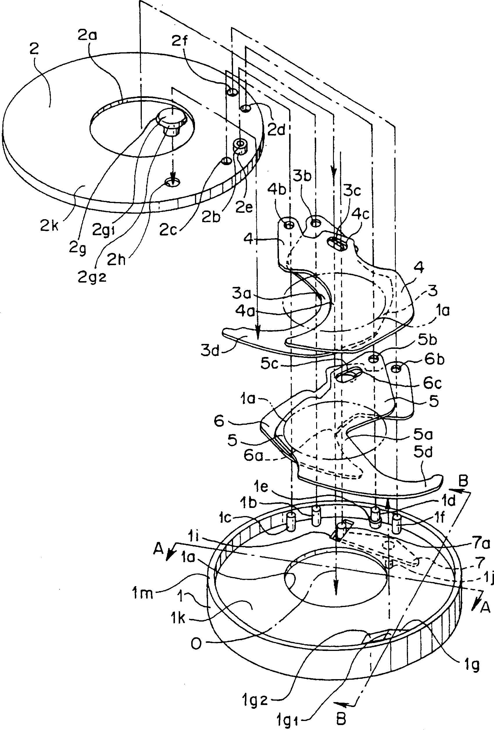
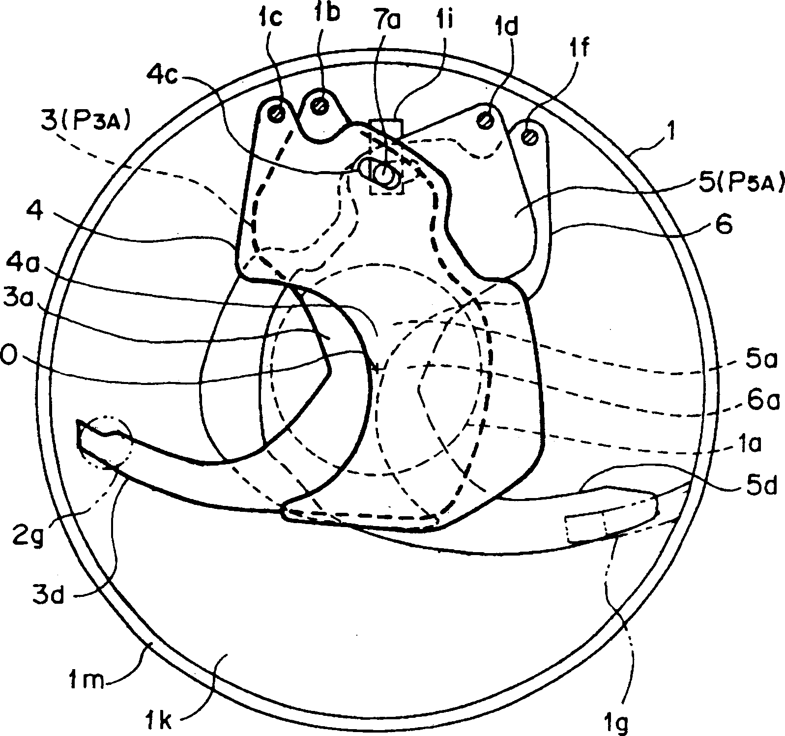
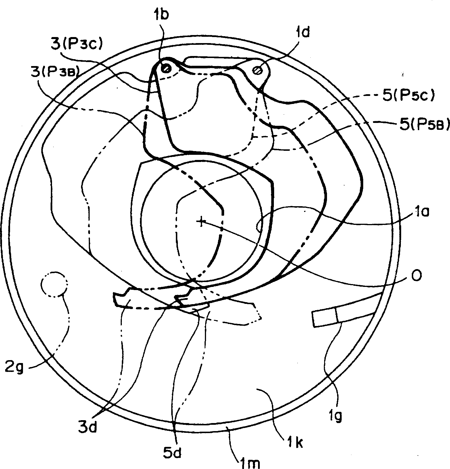
[0026] figure 1 It is an exploded perspective view of the shutter device according to the first embodiment of the present invention; figure 2 Viewed from the incident side, the plan view of the shutter device with the housing cover removed, the figure shows the main and auxiliary blades when the shutter is closed; image 3 Viewed from the incident side, the plan view of the housing cover of the shutter device above is removed, and only the main blades in the shutter open state are shown in the figure;

[0027] Figure 4 is the above figure 1 The A-A sectional view in the figure shows the closed state of the shutter of the above shutter device;

[0028] Figure 5 is the above figure 1 The B-B sectional view in the figure shows the closed state of the shutter of the above shutter device;

[0029] Figure 6 is the above figure 1 The A-A cross-sectional view in , however...


PUM


Abstract

Provided is a shutter unit which performs secure shutter operation while deterring shutter blades from bounding in opening / closing operation and is arranged in a small space. This shutter unit has main blades 3 and 5 and subordinate blades 4 and 6 which can rotate and travel in the space formed of a shutter case 1 and a case lid 2 in opening / closing directions; and the main blades 3 and 5 are provided with extension projection parts 3d and 5d and braking members 2g and 1g made of shock-absorbing raw materials are arranged opposite closure-state termination positions of the extension projection parts 3d and 5d separately from their movement traces across slight gaps. When this shutter unit is driven from the opening state to the closure state, the main blades 3 and 5 suddenly stop at their termination positions and when the extension projection parts 3d and 5d are displaced along the optical axis, they abut against the braking members 2g and 1g to be braked, so that the main blades 3 and 5 and subordinate blades 4 and 6 are deterred from bounding.

Description

technical field [0001] The present invention relates to a structure of a shutter device that opens and closes an exposure opening through which photographic light passes. Background technique [0002] In the past, in the shutter device that drives the blade switch of the shutter to open and close the opening for exposure, after the blade of the shutter rotates (moves) at a high speed, when it reaches the open position or the closed position, it is very difficult to quickly stop the blade. prone to rebound. The bounce of the shutter blades is the cause of changes in the exposure level or light leakage, which is undesirable. Therefore, various shutter devices equipped with a mechanism for preventing the rebound of the shutter blades have been proposed. [0003] The curtain shutter disclosed in Japanese Unexamined Patent Application Publication No. 9-5831 has an elastic buffer member, and this buffer member drives the rear curtain slit blades or the front curtain slit blades ...

Claims


Application Information

Patent Timeline
Patent Type & Authority Applications(China)
IPC IPC(8): G03B9/08G03B9/10G03B9/14G03B9/26
Inventor 高梨立男
Owner OLYMPUS CORP
Why Eureka
Try Eureka