Speaker verifying apparatus

A speaker and microphone technology, applied in the field of speaker verification devices, can solve problems such as complex structure configuration and complex processing of voice signals

Inactive Publication Date: 2004-08-18
KK TOSHIBA
View PDF2 Cites 2 Cited by
  • Summary
  • Abstract
  • Description
  • Claims
  • Application Information

AI Technical Summary

Problems solved by technology

[0005] However, with this technique, a complex voice-band signal must be generated which includes information about the date of occurrence etc. and is encrypted to prevent illicit decoding
Furthermore, complex processing must be performed on such voiceband signals to determine whether an overheard voice signal has been mistakenly used
As a result, devices using this technology have many complex structural configurations

Method used


Image

  • Speaker verifying apparatus
  • Speaker verifying apparatus
  • Speaker verifying apparatus

Examples


no. 1 example

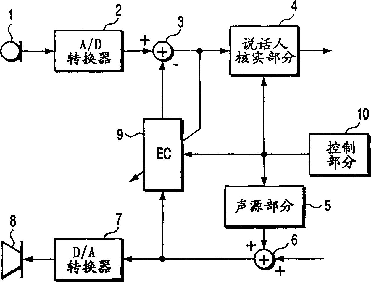
[0020] figure 1 is a block diagram of the configuration of the speaker verification device according to the first embodiment of the present invention.

[0021] Such as figure 1 As shown in , the speaker verification device according to the first embodiment of the present invention includes a microphone 1, an A / D converter 2, a subtractor 3, a speaker verification part 4, a sound source part 5, an adder 6, a D / A converter 7 , speaker 8 , echo canceller (EC) 9 , and control section 10 .

[0022] The microphone 1 outputs an audio signal corresponding to a surrounding sound, such as a voice given by a speaker. The A / D converter 2 digitizes the audio signal output by the microphone 1 . The audio signal output by the A / D converter 2 is input to the subtracter 3 .

[0023] The suppression signal output from echo canceller 9 is also input to subtractor 3 . Subtractor 3 subtracts this suppression signal from the audio signal output from A / D converter 2 .

[0024] The speaker ver...

no. 2 example

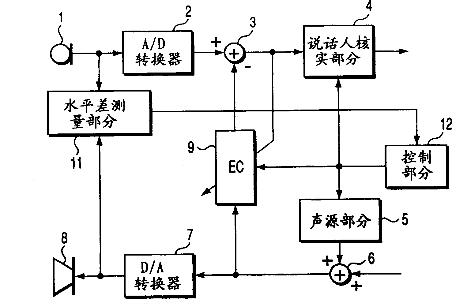
[0044] image 3 is a block diagram of a configuration of a speaker verification device according to a second embodiment of the present invention. exist image 3 in, with figure 1 The same components are denoted by the same reference numerals, and their detailed explanations will be omitted.

[0045] Such as image 3 As shown in , the speaker verification device according to the second embodiment includes a microphone 1, an A / D converter 2, a subtractor 3, a speaker verification section 4, a sound source section 5, an adder 6, a D / A conversion 7, speaker 8, echo canceller (EC) 9, level difference measuring section 11, and control section 12. That is, the speaker verification apparatus of the second embodiment differs from that of the first embodiment in that a control section 12 is used instead of the control section 10 and a level difference measurement section 11 is added.

[0046] The level difference measuring section 11 measures the difference between the audio signal...

no. 3 example

[0053] Figure 5 is a block diagram of a configuration of a speaker verification device according to a third embodiment of the present invention. exist Figure 5 in, with figure 1 The same components are denoted by the same reference numerals, and their detailed explanations will be omitted.

[0054] Such as Figure 5 As shown in , the speaker verification device according to the third embodiment includes a microphone 1, an A / D converter 2, a subtractor 3, a speaker verification section 4, a sound source section 5, an adder 6, a D / A conversion 7, loudspeaker 8, echo canceller (EC) 9 and control section 13. That is, the speaker verification device of the third embodiment differs from that of the first embodiment in that a control section 13 is used instead of the control section 10 .

[0055] The control section 13 includes, for example, a computer, and controls the operation of the speaker verification section 4, the sound source section 5, and the echo canceller 9, and c...


PUM


Abstract

When the speaker is registered or verified, the supplying part (5) outputs an interference sound signal to cause the loudspeaker (8) to emit interference sound. In the sound inputted to the microphone (1), the canceling part (3, 9) cancels the component corresponding to the interference sound fed back to the microphone (1). Using the sound in which the component corresponding to the interference sound has been canceled, the collating part (4) registers or verifies the speaker.

Description

technical field [0001] The present invention relates to a speaker verification device which checks the speaker with registered speakers based on the speaker's voice. Background technique [0002] Checking a previously registered voice signal with a newly input voice signal is disclosed in Japanese Patent Application Laid-Open Publication No. 2000-59501. [0003] However, with this technique, when the voice of a verified speaker is recorded in some way, it is possible for another person to use the recorded voice to carry out fraudulent claims. [0004] A technique for preventing illegal activities by eavesdroppers using a voice band signal having a specific frequency spectrum representing the date of occurrence or the like is disclosed in Japanese Patent Application Laid-Open Publication No. 10-107790. [0005] However, with this technique, it is necessary to generate a complex voiceband signal which includes information on the date of occurrence etc. and which is encrypted ...

Claims


Application Information

Patent Timeline
Patent Type & Authority Applications(China)
IPC IPC(8): G10L15/00G10L15/06G10L15/065G10L15/07G10L15/20G10L15/28G10L17/00G10L17/02G10L17/06G10L21/0208H04M9/08
CPCH04M9/082G10L21/0208G10K11/175G10L17/02
Inventor 井阪岳彦三关公生
Owner KK TOSHIBA
Why Eureka
Try Eureka