Fusion splicing device and fusion splicing method

A fusion splicing equipment, fusion splicing technology, applied in the direction of instruments, optics, light guides, etc., can solve problems such as difficult to identify optical fibers

Inactive Publication Date: 2004-09-22
SUMITOMO ELECTRIC IND LTD
View PDF1 Cites 21 Cited by
  • Summary
  • Abstract
  • Description
  • Claims
  • Application Information

AI Technical Summary

Problems solved by technology

Thus, while this technique is effective when the brightness profile differs significantly depending on the type of fiber, it is difficult to identify all types of fiber

Method used


Image

  • Fusion splicing device and fusion splicing method
  • Fusion splicing device and fusion splicing method
  • Fusion splicing device and fusion splicing method

Examples


Embodiment Construction

[0021] The best way to carry out the invention

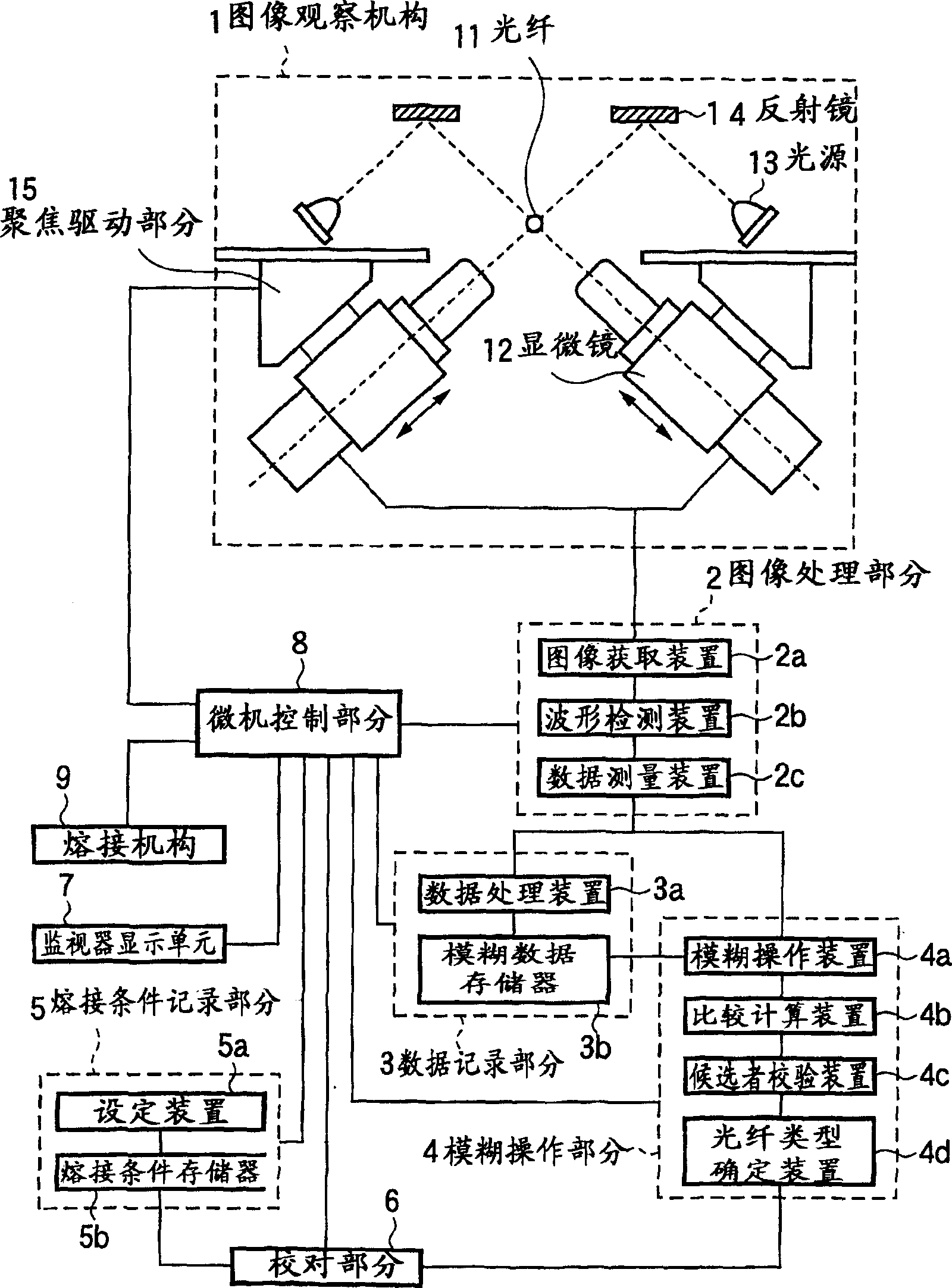
[0022] figure 1 is a block diagram for explaining an embodiment of the present invention. exist figure 1 Among them, the symbol 1 represents the image observation mechanism, the symbol 2 represents the image processing part, the symbol 3 represents the data recording part, the symbol 4 represents the fuzzy operation part, the symbol 5 represents the welding condition recording part, the symbol 6 represents the proofreading part, and the symbol 7 represents the monitor display Unit, reference numeral 8 represents the control part, reference numeral 9 represents the fusion splicing mechanism, reference numeral 11 represents the optical fiber, reference numeral 12 represents the microscope, reference numeral 13 represents the light source, reference numeral 14 represents the reflector, and reference numeral 15 represents the focus driving part.

[0023] The image observation mechanism 1 uses a microscope 12 with a CCD camera arra...


PUM


Abstract

The purpose of the present invention is to provide a method and device which can discriminate all kinds of the optical fibers and carry out the melting-connection using the connection conditions suitable to the various optical fibers. The present invention is the melting-connection device which melt-connects through the discharge by pressing near the end portion of the optical fiber, and it is provided with: the image observation mechanism (1) which observes the end portion of the optical fiber; the image treatment department (2), which measures the parameter data of the illumination distribution waveform of the optical fiber cross section based on the image taken; the fuzzy-calculation-department (4) which identifies the optical fiber categories through the correlations obtained by fuzzy-calculating the fuzzy-calculation data by registering the measured parameter data in the registration department (3) in advance; the cross-reference department (6) which cross-references the identified optical fiber category to the optical fiber category melting-conditions registered in the melting-connection-condition-registration-department (5) prepared in advance; the display device (7) which displays the results of the cross-references; the melting-connection mechanism (9); and the control department (8).

Description

field of invention [0001] The present invention relates to an apparatus and method for fusing the ends of communication optical fibers by electric discharge heating or the like, and more particularly to an apparatus and method for fusing optical fibers under fusion splicing conditions suitable for the type of optical fiber by automatically determining the type of optical fiber. method. Background of the invention [0002] In recent years, with the expansion and diversification of optical fiber communication, various types of optical fibers for various purposes have been developed and utilized. Various types of optical fiber are available, including single-mode optical fiber (hereinafter referred to as SM optical fiber), multimode optical fiber (hereinafter referred to as MM optical fiber), dispersion-shifted optical fiber (hereinafter referred to as DS optical fiber), and erbium-doped optical fiber (hereinafter referred to as ED fiber). When these optical fibers are splice...

Claims


Application Information

Patent Timeline
Patent Type & Authority Applications(China)
IPC IPC(8): G02B6/255G02B6/38
CPCG02B6/2553G02B6/2551G02B6/2555G02B6/255
Inventor 服部一成
Owner SUMITOMO ELECTRIC IND LTD
Why Eureka
Try Eureka