Air bag system

A technology of airbags and air vents, which is applied in vehicle safety arrangement, pedestrian/passenger safety arrangement, transportation and packaging, etc. It can solve the problems of increased production cost and increased man-hours of processing, and achieves the goal of reducing the number of parts and softly restraining Effect

Inactive Publication Date: 2004-10-20
HONDA MOTOR CO LTD
View PDF1 Cites 10 Cited by
  • Summary
  • Abstract
  • Description
  • Claims
  • Application Information

AI Technical Summary

Problems solved by technology

[0006] However, with the aforementioned conventional air bag system, since a special seal is required to close the vent hole in the air bag, there arises a problem that the number of parts and the number of man-hours for processing are limited to some extent by the additional seal. increase, thereby increasing production costs

Method used


Image

  • Air bag system
  • Air bag system
  • Air bag system

Examples


Embodiment Construction

[0020] The mode of carrying out the present invention will be described below based on the embodiments shown in the drawings.

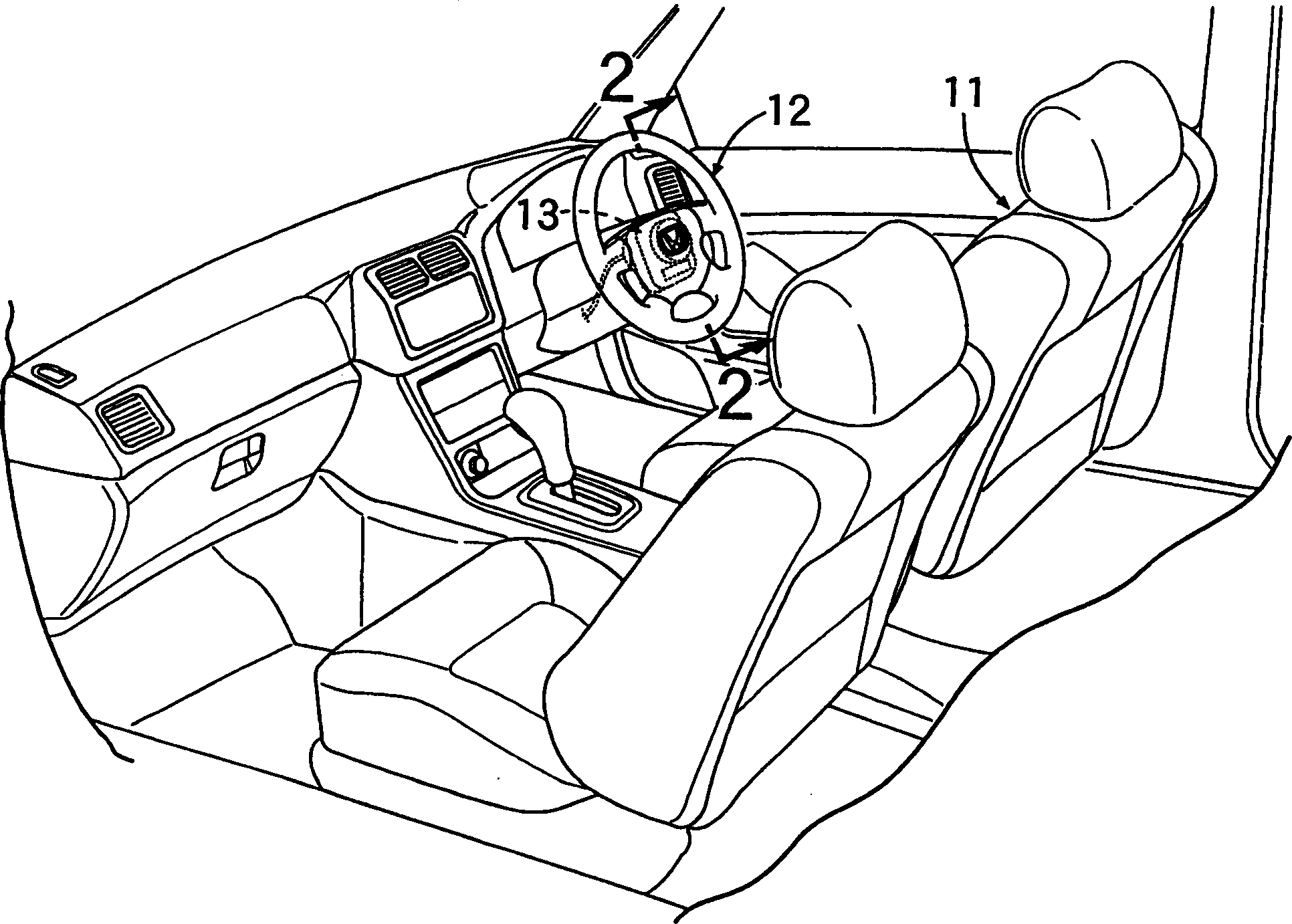
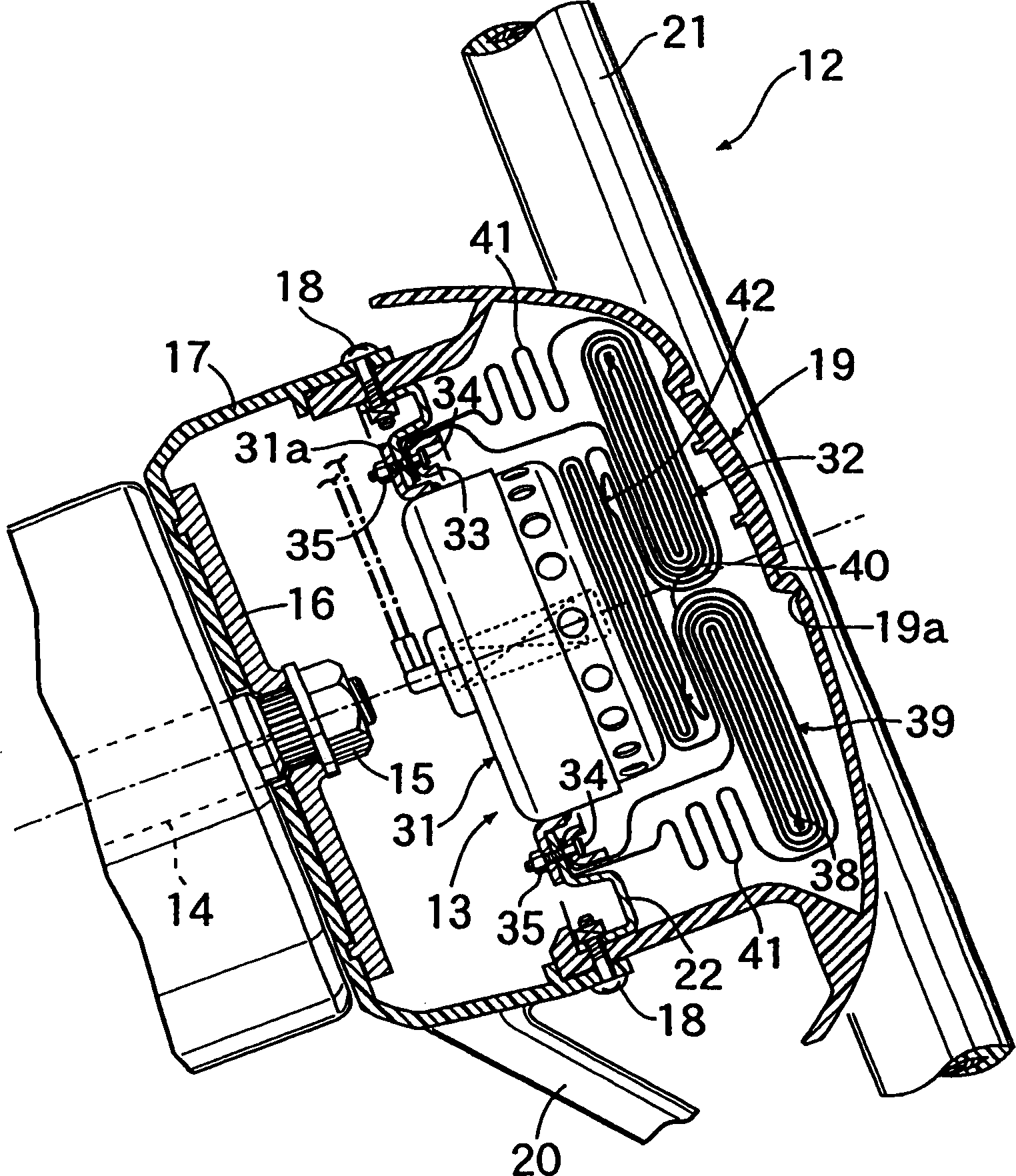
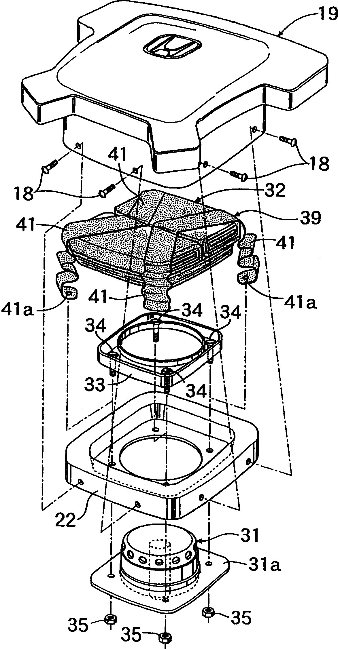
[0021] Figure 1 to Figure 7 A first embodiment is shown, where figure 1 is a perspective view of the front of the passenger compartment of a car, figure 2 is along figure 1 An enlarged sectional view taken along the midline 2-2, image 3 is an exploded perspective view of an airbag assembly, Figure 4 is an exploded perspective view of an airbag, Figure 5 is an explanatory diagram that explains when the airbag deploys (from Image 6 When viewed from the direction indicated by the middle arrow 5), the action of the airbag, Image 6 From Figure 5 The view from the direction indicated by the arrow 6, and Figure 7 is an explanatory diagram that explains the action of the airbag when the restrictive fabric is ruptured, and is the same as Figure 5 correspond.

[0022] like figure 1 As shown, an airbag module 13 for a driver's seat 11 is acc...


PUM


Abstract

A restricting member 39 disposed along an outer surface of an air bag 32 restricts an axial inflation of the air bag 32 in an earlier stage of deployment of the air bag 32, and in a later stage of deployment, the restricting member 39 allows for the inflation of the air bag 32 to its maximum capacity through breakage of brittle portions 41b. In the deployment process of the air bag 32, since vent holes 37b formed in a base fabric 37 of the air bag 32 are closed by the restricting member 39, the leakage of gas from the vent holes 37b is prevented to thereby enable a quick deployment of the air bag 32. Then, when the brittle portions 41b on the restricting member 39 break, the vent holes 37b are opened.

Description

technical field [0001] The present invention relates to an airbag system in which a folded airbag and an inflator are supported on a retainer so that the airbag is deployed into a passenger compartment of a vehicle by being inflated by gas generated by the inflator when a collision occurs. Background technique [0002] An airbag for being deployed into a passenger compartment of a vehicle by gas supplied from an inflator when a vehicle collides has an exhaust hole, and when the internal pressure of the inflated airbag increases due to restraining the occupant, the supplied gas passes through The vent vents, thereby reducing the tension in the base fabric of the airbag. In this way, not only is the occupant comfortably restrained, but the base fabric is prevented from tearing. [0003] In the case where the vent hole is formed by a simple hole opened in the base fabric, there is a possibility that gas leaks from the vent hole during the inflation of the airbag by the gas sup...

Claims


Application Information

Patent Timeline
Patent Type & Authority Applications(China)
IPC IPC(8): B60R21/16B60R21/203B60R21/233B60R21/2338B60R21/239
CPCB60R2021/23386B60R21/239B60R21/2338B60R21/203
Inventor 甲斐健
Owner HONDA MOTOR CO LTD
Why Eureka
Try Eureka