
Asymmetric double coil type permanent-magnetic mechanism

A permanent magnet mechanism and double-coil technology, applied in high-voltage air circuit breakers, electrical components, electric switches, etc., can solve the problem of low holding force, high closing holding force, and increased load on the power supply control unit by the peak current of the opening coil and other problems, to achieve the effect of large holding force, increased closing holding force, and faster movement speed

Active Publication Date: 2004-11-03
XI AN JIAOTONG UNIV
View PDF0 Cites 11 Cited by
  • Summary
  • Abstract
  • Description
  • Claims
  • Application Information

AI Technical Summary

Problems solved by technology

Excessive peak current of the opening coil increases the burden on the power supply control unit of the permanent magnet mechanism composed of power electronic devices, causing difficulties in the design of the control unit
Another disadvantage of the existing permanent magnet mechanism with a symmetrical structure of the opening and closing coils is that when the moving iron core is in the closing position, its holding force is close to the holding force of the moving iron core in the opening position, that is, when the moving iron core moves to the left. For the circuit breaker, the closing position requires a high closing holding force due to the need to overcome the reaction force of the contact spring and the reaction spring, while in the opening position, the reaction force is small and the required holding force is very low. There are symmetrical structures where the holding force in two positions cannot match the actual requirements

Method used


Image

  • Asymmetric double coil type permanent-magnetic mechanism

Examples


Embodiment Construction

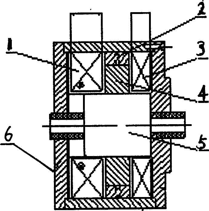
[0008] Referring to the accompanying drawings, the present invention includes a moving iron core 5 arranged in a casing 6, on which the opening coil 1 and closing coil 3 of different cross-sections are set, and between the opening coil 1 and the closing coil 3 there is a An intermediate magnetic pole composed of permanent magnet 2 and magnetic conductor 4 is provided, the thickness of opening coil 1 is greater than that of closing coil 3 , and the intermediate magnetic pole composed of permanent magnet 2 and magnetic conductor 4 is biased towards closing coil 3 .

[0009] The working principle of the present invention is as follows: if the moving iron core 5, that is, the circuit breaker is in the closing position, after the power supply unit composed of power electronic devices receives the opening signal, the power supply unit supplies power to the opening coil 1, and the magnetic field force generated by the opening coil 1 Offset the closing holding force, so that the moving...


PUM


Abstract

An asymmetric double coil permanent magnetic unit includes a moving iron core in a case, an open coil and a closing coil sleeved on the core with a mid-magnetic pole in between and the open coil is wider than the closing coil close to the mid-magnetic pole. When the core is at the closing position, the power unit supplies power to the open coil after receiving open signals and the magnetic field force generated by open coil balances the kept closing force, the core drives the breaker to open it to cut off the open coil and remains at the open position relying on the permanent magnetic force. The closing of the breaker depends on the excitation of the closing coil. This invention increases the cross section and turn numbers of the open coil and speeds up its velocity, the asymmetrical paths for right and left of the mid pole increase the closing force generated by the magnet.

Description

technical field [0001] The invention belongs to the field of switching appliances, in particular to an asymmetric double-coil permanent magnet mechanism for opening and closing coils used for vacuum circuit breaker operations. Background technique [0002] Due to its simple structure and high reliability, the permanent magnet operating mechanism of vacuum circuit breakers introduced in recent years is gradually replacing the existing spring operating mechanism and has been popularized in medium-voltage systems. The cross section of the opening and closing coils of the existing permanent magnet mechanism is the same, and there are two types of permanent magnet operating mechanisms with symmetrical structures: cylindrical and flat. The power supply unit provides the opening and closing excitation of the opening and closing coils. The ferromagnet The part includes: the middle magnetic pole composed of permanent magnet and magnetizer; moving iron core and shell. The middle magn...

Claims


Application Information

Patent Timeline
Patent Type & Authority Applications(China)
IPC IPC(8): H01H3/28H01H33/38H01H33/666
Inventor 陈德桂游一民
Owner XI AN JIAOTONG UNIV
Learn More