B-dot probe based on PCB type magnetic induction coil, and current spatial distribution measuring system

A technology of magnetic induction coil and current probe, which is applied in the direction of measuring device, only measuring current, measuring electric variable, etc., can solve the problems of large difference in sensitivity of B-dot, inconvenient data analysis, and difficulty in ensuring the consistency of B-dot magnetic induction coil. , to achieve the effect of suppressing strong electromagnetic and high-energy electronic interference, simple structure design, and good electrical connection

Active Publication Date: 2016-03-09
NORTHWEST INST OF NUCLEAR TECH
View PDF6 Cites 6 Cited by
  • Summary
  • Abstract
  • Description
  • Claims
  • Application Information

AI Technical Summary

Problems solved by technology

However, the magnetic induction coil of the current B-dot probe is usually wound into a small ring with enameled wire or steel core cable. Beam Dynamics Study Brings Great Inconvenience

Method used


Image

  • B-dot probe based on PCB type magnetic induction coil, and current spatial distribution measuring system
  • B-dot probe based on PCB type magnetic induction coil, and current spatial distribution measuring system
  • B-dot probe based on PCB type magnetic induction coil, and current spatial distribution measuring system

Examples


Embodiment Construction

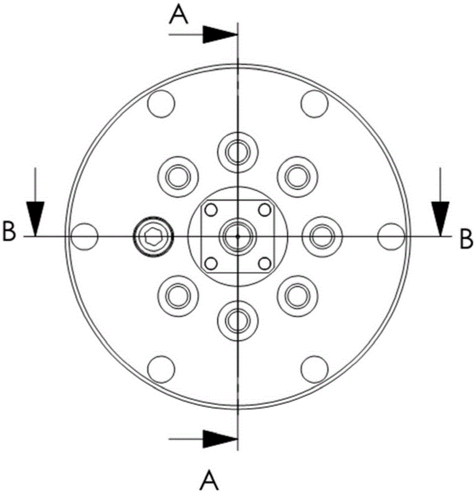
[0045] The present invention proposes a B-dot current probe using a small-sized printed circuit board (PCB) as a magnetic induction coil. tin. The wiring on the top layer of the coil starts at the center of the top layer of the PCB, and the wiring on the bottom layer of the coil terminates in the tinned area of ​​the PCB board. The male TNC connector snaps into the recess of the PCB coil and leads out the measurement signal. The metal support ring 3 engraved with a rectangular groove and the metal shielding cover 2 press the PCB type magnetic induction coil 1 from the upper and lower sides to ensure good electrical contact. A slit 7 is opened on the top of the metal shielding cover 2, and the direction of the slit coincides with the normal direction of the PCB coil, allowing the magnetic field to enter the PCB coil. The connector mounting flange 4, the metal support ring 3 and the metal shielding cover 2 are fastened and connected by screws. The implementation technical sol...


PUM


Abstract

The invention provides a B-dot probe based on a PCB type magnetic induction coil, and a current spatial distribution measuring system. A magnetic induction coil of the B-dot probe is clockwise or anticlockwise wired in the same direction on the circuit board, so that the PCB type magnetic induction coil is formed. Substantial advantages are achieved when an array formed by the plurality of B-dot probes is used to measure the current spatial distribution uniformity. A metal shielding cover is arranged on the top end, is buckled with a metal support ring and is fastened through fastening screws. A narrow gap is further formed in the metal shielding cover. The direction of long edges of the narrow gap is perpendicular to the plane of the magnetic induction coil. The metal shielding cover inhibits strong electromagnetic and strong radiation interference and also enables a magnetic field to be introduced to the magnetic induction coil through the narrow gap.

Description

technical field [0001] The invention proposes a B-dot current probe and a current measurement system, which have important applications in the measurement of fast pulse currents such as ultra-high power pulse transmission, vacuum magnetically insulated transmission lines, induced voltage superimposed devices, and Z-pinch experiments. Background technique [0002] Ultra-high power pulse technology can obtain extreme physical experimental conditions such as extreme high temperature, high pressure, high energy density and strong radiation in the laboratory, and has important applications in cutting-edge scientific research such as Z-pinch inertial confinement fusion, radiation effects and astrophysics. Beam transmission measurement is an indispensable link in the operation monitoring, parameter measurement and physical experiments of large pulsed power devices. [0003] The pulse current (beam current) measurement in the ultra-high power pulse device has the following character...

Claims


Application Information

Patent Timeline
Patent Type & Authority Applications(China)
IPC IPC(8): G01R19/00
CPCG01R19/0061G01R19/0092
Inventor 魏浩孙凤举姜晓峰丛培天邱爱慈
Owner NORTHWEST INST OF NUCLEAR TECH
Why Eureka
Try Eureka