Gun trigger lock

A technology for trigger locks and guns, applied in the field of gun locks, can solve the problems that the safety lock cannot be opened or locked, the fingerprint identification method is single, and the gun unlocking operation is inconvenient. Effect

Inactive Publication Date: 2016-02-17
FENGHUA JINFENG MACHINERY
View PDF5 Cites 6 Cited by
  • Summary
  • Abstract
  • Description
  • Claims
  • Application Information

AI Technical Summary

Problems solved by technology

Compared with the traditional mechanical gun lock, the gun smart safety lock uses fingerprint recognition to open the safety lock, which improves the safety of gun use and is easy to operate. There are still some urgent technical problems that need to be solved, and these problems may have a serious impact on actual use
For example, when the safety lock is opened, the left lock seat and the right lock seat cannot be separated automatically, and can only be separated from each other manually, which brings inconvenience to the unlocking operation of the gun; the safety lock uses a motor to directly drive the locking mechanism to act , which has high requirements on the motor and battery, and it needs a motor with a large output power to be able to realize it; the fingerprint recognition starts in a relatively simple way, such as a battery shortage or a mechanical structure failure, which may cause the problem that the safety lock cannot be opened or locked

Method used


Image

  • Gun trigger lock
  • Gun trigger lock
  • Gun trigger lock

Examples


Embodiment 1

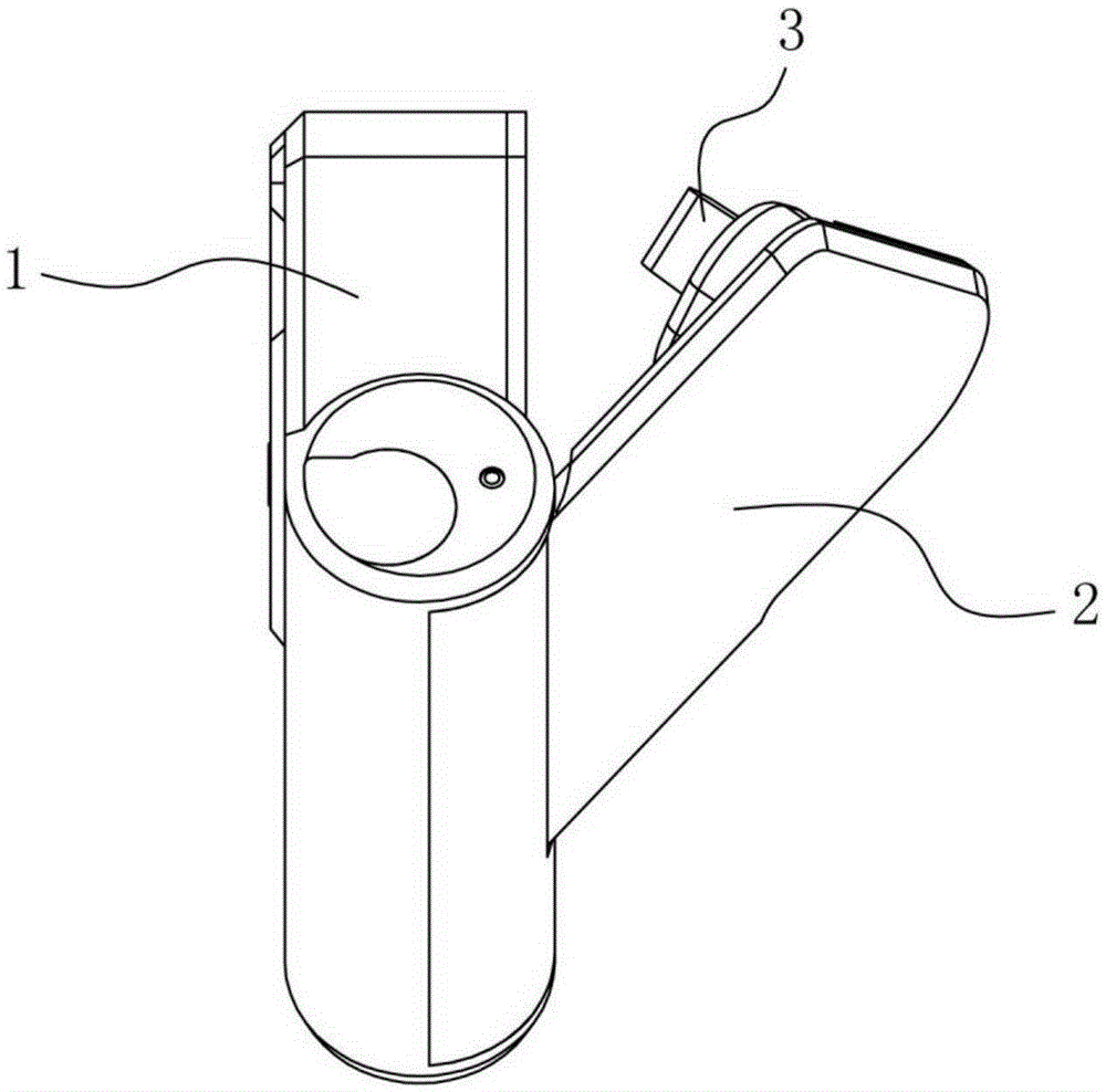
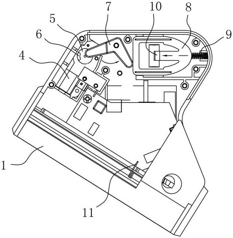
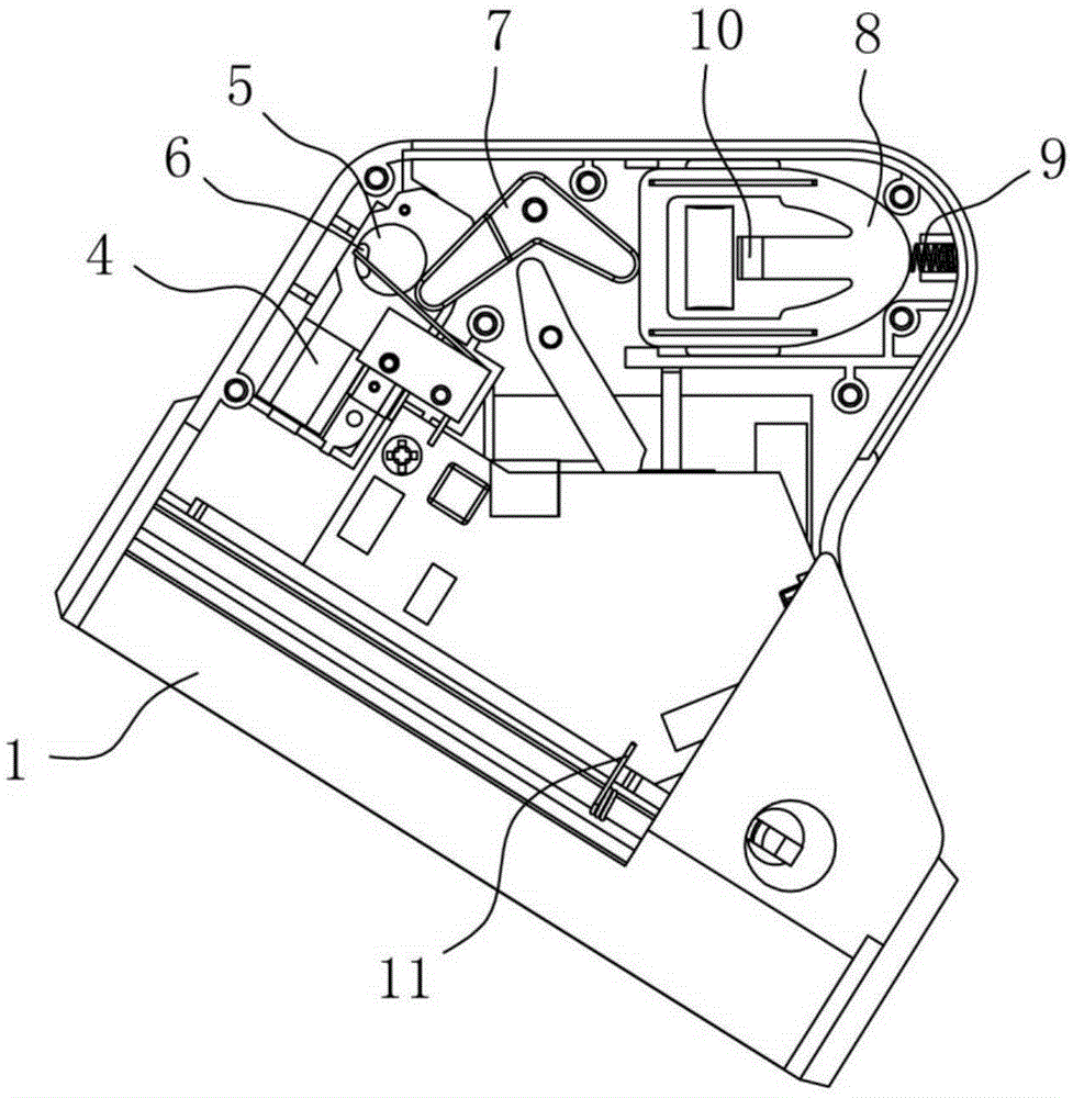
[0030] A firearm trigger lock, comprising a lock body 1, one side of the lock body 1 is provided with a lock cover 2 which can be turned over relative to it, and the lock body 1 is provided with an identification device, a control circuit board, a driving device, a locking mechanism and a power supply module, the identity recognition device is used to collect user identity information and send it to the control circuit board, the control circuit board controls the action of the drive device according to the comparison result of the identity information, the drive device drives the action of the locking mechanism, and the power module supplies the identity recognition device, The control circuit board and the driving device are powered; the lock cover 2 is provided with a pinch plate 3 that is engaged with the locking mechanism. When the pinch plate 3 of the lock cover 2 is engaged with the locking mechanism of the lock body 1, the trigger ring of the gun is locked It is arrange...

Embodiment 2

[0035]A more optimal solution, on the basis of Embodiment 1, the power module has a delayed power-off function, the lock body 1 is also provided with a wake-up button 13 connected to the power module, the wake-up button 13 Used for the power supply module to restore power supply. The delayed power-off function of the power module can effectively reduce power consumption. For example, within the set time, except for pressing the wake-up button 13, the identification device disconnects the power supply of the power module without any operation. When the power module disconnects the power supply , you can only operate by pressing the wake-up module first. Further, the wake-up button 13 is arranged on the lock body 1 adjacent to the identification device, which is more convenient for operation. Preferably, the wake-up button 13 can also be replaced with infrared sensing or touch sensing to perform the wake-up operation.

Embodiment 3

[0037] Another more optimal solution, on the basis of Embodiment 1 or Embodiment 2, the lock body 1 is also provided with a mechanical emergency unlocking mechanism, the mechanical emergency unlocking mechanism includes a lock cylinder connecting rod 14 and a transmission linkage Rod 15, the lock body 1 is provided with a lock cylinder insertion hole 16, the lock cylinder connecting rod 14 is rotatably arranged on the lock body 1 along the lock cylinder insertion hole 16, and the transmission linkage 15 is rotatably arranged through a pivot shaft On the lock body 1, one end of the transmission link 15 is connected with the lock cylinder link 14, and the other end of the transmission link 15 is in transmission cooperation with the locking mechanism. In this scheme, a mechanical emergency unlocking mechanism is added, and when the firearm trigger lock fails, it can be opened by the mechanical emergency unlocking mechanism. Specifically, insert the special key into the lock cylin...


PUM


Abstract

The invention discloses a gun trigger lock which comprises a lock body and a locking cover capable of being turned over relative to the lock body. The lock body is provided with an identity recognition device, a control circuit board, a drive device, a locking mechanism and a power source module. The identity recognition device is used for acquiring user identity information and sending the user identity information to the control circuit board. The control circuit board controls the drive device to act according to the comparison result of the identity information. The drive device drives the locking mechanism to act. The power module supplies power to the identity recognition device, the control circuit board and the drive device. The lock cover is provided with a buckle plate bucked to the locking mechanism. The gun trigger lock drops out when opened and is convenient to operate. A miniature worm and gear motor is adopted to drive the locking mechanism and is small in size, low in output power and beneficial to lightweight and miniaturization of the gun trigger lock. The gun trigger lock is further provided with a mechanical emergency unlocking mechanism. The gun trigger lock can be unlocked through the mechanical emergency unlocking mechanism under the emergency condition. A fingerprint unlocking manner, a sound unlocking manner, an RFID unlocking manner, a Bluetooth unlocking manner and the like can be selected and used for the identity recognition device.

Description

technical field [0001] The invention relates to the technical field of firearm locks, in particular to a firearm trigger lock. Background technique [0002] Guns are controlled weapons and have serious lethality. They need to be kept strictly and cannot be used by unauthorized people, otherwise troubles will arise. If the gun does not have a safety lock, it is easy to misuse the trigger and cause a fire, or it will be used illegally by others, which will cause serious consequences. The gun safety lock can lock the trigger part of the gun so that it cannot be used casually. [0003] See Chinese patent CN104034203A, which discloses an intelligent safety lock for firearms. The structure of the safety lock mainly includes a left lock seat and a right lock seat which are interlocked. At the trigger position, a control circuit board, a locking mechanism and a motor are arranged inside the right lock seat, and a fingerprint acquisition board is arranged on the housing of the right...

Claims


Application Information

Patent Timeline
Patent Type & Authority Applications(China)
IPC IPC(8): F41A17/46G07C9/00
CPCF41A17/46G07C9/00563
Inventor 竺开明李峰
Owner FENGHUA JINFENG MACHINERY
Why Eureka
Try Eureka