Display apparatus drive circuit having plurality of cascade connnected drive ics

A display device and drive circuit technology, applied to instruments, dining table utensils, home appliances, etc., can solve problems such as data cannot be correctly latched, data cannot be received correctly, and duty cycle changes

Inactive Publication Date: 2004-12-01
RENESAS ELECTRONICS CORP
View PDF2 Cites 13 Cited by
  • Summary
  • Abstract
  • Description
  • Claims
  • Application Information

AI Technical Summary

Problems solved by technology

As for the duty cycle of the data, there is no control over it, so that the duty cycle changes and causes the problem that the data cannot be latched correctly
In addition, phase adjustment among the enable signal, data, and clock signals is not performed, thereby causing a problem that data cannot be received correctly when data is received in response to the enable signal

Method used


Image

  • Display apparatus drive circuit having plurality of cascade connnected drive ics
  • Display apparatus drive circuit having plurality of cascade connnected drive ics
  • Display apparatus drive circuit having plurality of cascade connnected drive ics

Examples


Embodiment Construction

[0022] An embodiment of the present invention will be described below with reference to the accompanying drawings. The present invention is specifically described by the description of the embodiments.

[0023] 【Example】

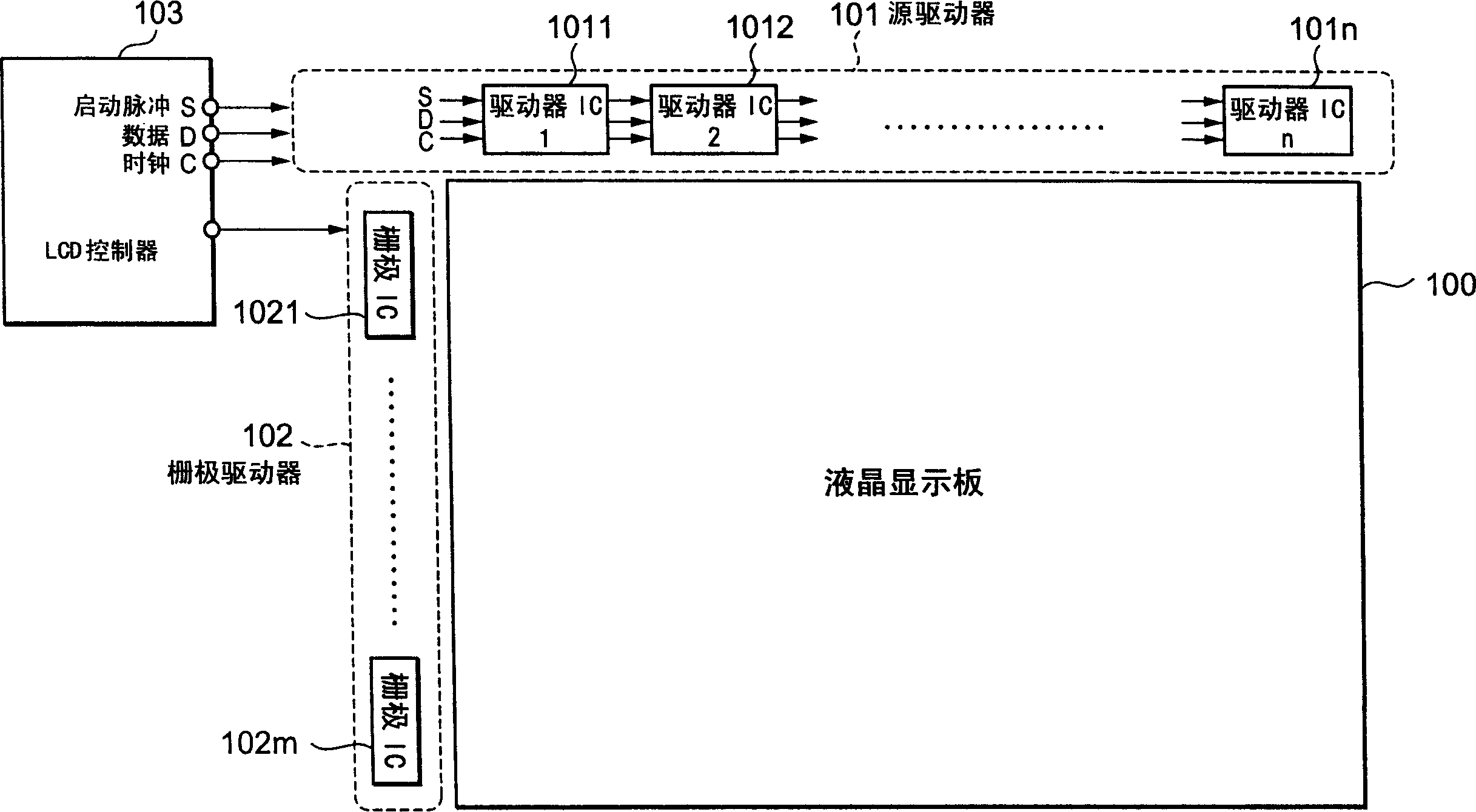
[0024] Such as figure 1 As shown, the system comprising the display device driving circuit of the present invention includes: a display panel 100 such as liquid crystal or plasma; a display device driving circuit (source driver) 101 for providing pixel data to the display panel 100; a gate driver 102, Used to drive the gates of pixels corresponding to one horizontal scanning line of the display panel 100, and provide data from the source driver 101 to the pixels; and a controller 103, used to provide the source driver 101 with a start pulse S, data D and clock C, and provide the gate driver 102 with a scanning horizontal synchronization signal.

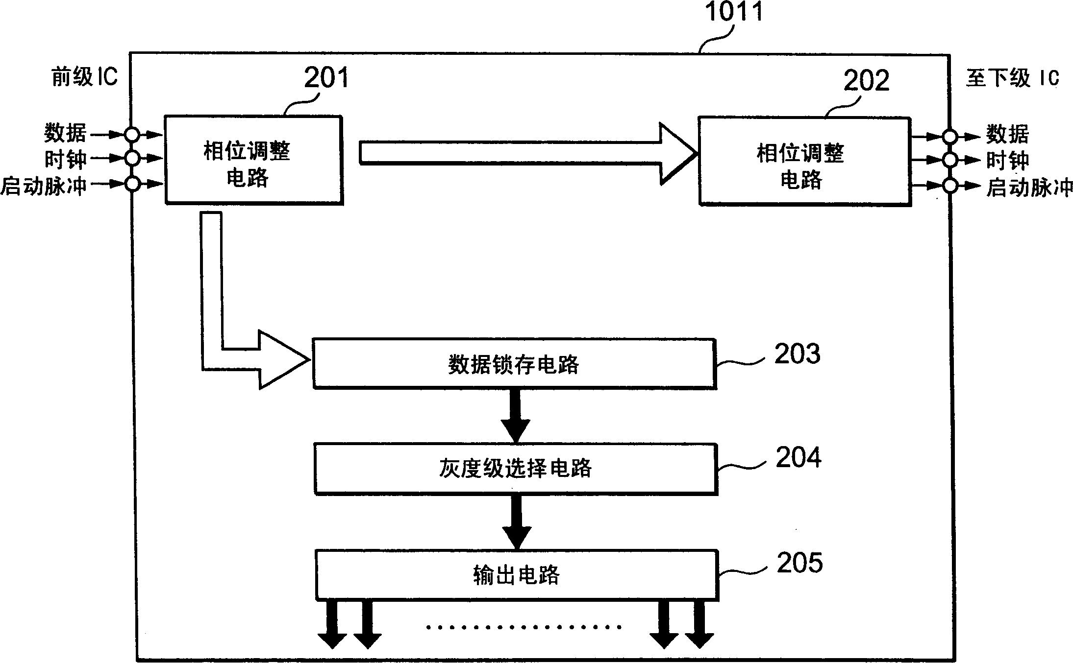
[0025] The source driver 101 includes cascaded driver ICs 1011 to 101n. This driver IC 1011 receives the sta...


PUM


Abstract

To prevent a timing shift of a clock and data supplied to a driver IC. A driver 1011 includes a phase adjustment circuit 201 for receiving via input terminals a clock and data outputted from a controller 103, latching received data with the clock adjusted to a 50-percent duty ratio, and outputting as phase-adjusted signals the data having the latched data further latched by synchronizing it with a delay clock having the duty-ratio-adjusted clock delayed by (pi / 2) and the clock of the 50-percent duty ratio.

Description

technical field [0001] The present invention relates to a display device driving circuit, in particular, the present invention relates to a display device driving circuit having a plurality of cascaded driver ICs (Integrated Circuits). Background technique [0002] In recent years, the size of display panels has been increasing, and a display device driving circuit for driving a display device having a plurality of cascaded driver ICs has attracted attention. [0003] For such driver ICs, usually, Figure 7 The driver IC shown is generally known as prior art (for example, see Patent Document 1). [0004] Figure 7 The illustrated driver IC 701 includes a phase adjustment circuit 702 , a data latch circuit 703 , a grayscale selection circuit 704 , and an output circuit 705 . [0005] The phase adjustment circuit 702 receives display data and a clock from an LCD controller not shown, performs phase adjustment, and then transfers the data to the next-stage driver IC, and also ...

Claims


Application Information

Patent Timeline
Patent Type & Authority Applications(China)
IPC IPC(8): G02F1/133G09G3/20G09G3/36G09G5/00
CPCG09G5/008G09G2300/04G09G5/006G09G2310/0275G09G2370/08A47G21/02A47G21/103
Inventor 赤堀英树
Owner RENESAS ELECTRONICS CORP
Why Eureka
Try Eureka