Cavity component

A technology of cavities and components, applied to building components, building structures, floors, etc., can solve problems such as cracking damage, complex stress on floors, and stress concentration

Inactive Publication Date: 2004-12-08
湖南邱则有专利战略策划有限公司
View PDF3 Cites 3 Cited by
  • Summary
  • Abstract
  • Description
  • Claims
  • Application Information

AI Technical Summary

Problems solved by technology

However, after this kind of cavity component is applied to the floor, at the corner of the cavity component, the force of the floor is more complicated, the stress is more concentrated, and cracks are easy to occur, and even cracking and damage

Method used


Image

  • Cavity component
  • Cavity component
  • Cavity component

Examples


Embodiment Construction

[0080] The present invention will be further described below in conjunction with the accompanying drawings and embodiments.

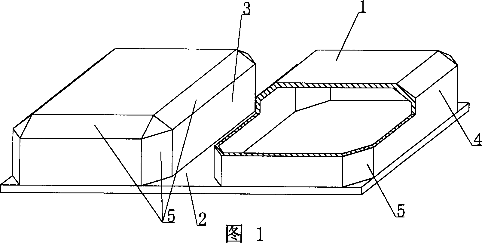
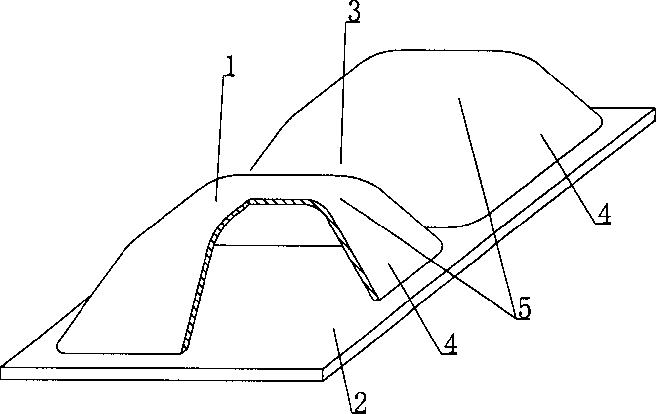
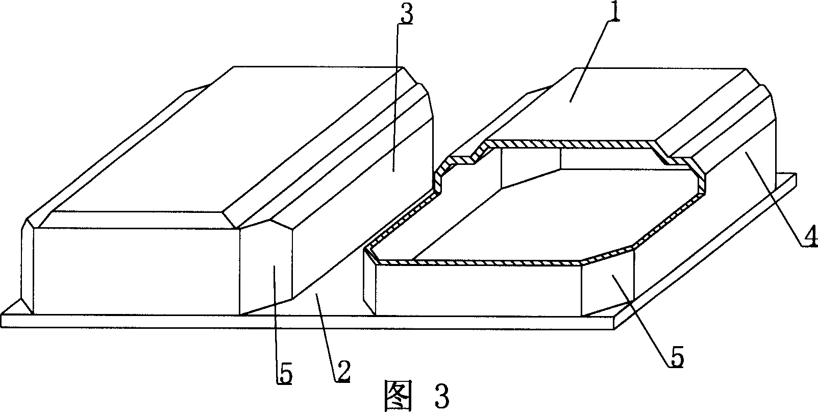
[0081] As shown in the accompanying drawings, the present invention includes a cavity formwork 1 and a base plate 2, the cavity formwork 1 and the base plate 2 are connected as a whole, and at least two cavity formworks 1 are arranged alternately on the base plate 2, and its side faces and the base plate 2 Constitute at least one cast-in-place structure inner rib mold cavity 3, and the other outer side 4 of the cavity formwork 1 constitutes the side formwork of the cast-in-place structure outer rib or beam or wall, which is characterized in that at least one corner of the cavity formwork 1 Set with chamfer 5. Fig. 1 is a schematic structural diagram of Embodiment 1 of the present invention. In the accompanying drawings, 1 is a cavity formwork, 2 is a bottom plate, 3 is an inner rib cavity of a cast-in-place structure, 4 is an outer surface, and 5 is a ...


PUM


Abstract

A hollow component consists of a substrate and several hollow molded chambers on it uniformly. Two, at least, molded chambers arranged in space. One, at least, inner molding rib chamber formed by sidewall of each chamber and the substrate is cast in site. The outer molding surface of the chamber is formed to be rib, beam or wall cast in site. The chamber has one chamfer, at least, at its edges to be cast in site into column or reinforcing rib to eliminate stress concentration and prevent from fractures and to bear larger concentrative load. It has some advantages such as: simple structure, high strength, easy to construct, low cost, and available in hollow floors, roofs, foundation substrates, walls and bridge beams of concrete cast in site.

Description

(1) Technical field [0001] The present invention relates to a cavity member. (2) Background technology [0002] At present, most buildings with brick-concrete structure and reinforced concrete structure use prefabricated hollow slabs as floor slabs, which have the advantages of fast construction speed and low cost. However, because there is no firm connection between two adjacent prefabricated hollow slabs, only cement mortar is used to fill the joints, so the integrity is poor, which is not conducive to earthquake resistance, and cracks and water seepage often occur in the gaps. In order to solve the above problems, many buildings adopt the method of cast-in-place concrete floor slabs (solid and hollow). Although the problems of earthquake resistance and cracking have been solved, a large number of templates are used during construction, which not only increases the cost, but also slows down the construction speed and prolongs the construction period. deadline. Applicatio...

Claims


Application Information

Patent Timeline
Patent Type & Authority Applications(China)
IPC IPC(8): E04B5/36
Inventor 邱则有
Owner 湖南邱则有专利战略策划有限公司
Why Eureka
Try Eureka