Hollow cavity member

A cavity and component technology, used in building components, building structures, floor slabs, etc., can solve problems such as poor overall strength and rigidity, and cavity mold shell rupture.

Inactive Publication Date: 2006-08-23
湖南邱则有专利战略策划有限公司
View PDF3 Cites 2 Cited by
  • Summary
  • Abstract
  • Description
  • Claims
  • Application Information

AI Technical Summary

Problems solved by technology

However, because there is no reinforced structure in the cavity formwork, the overall strength and rigidity of the cavity components are poor, and the cavity formwork is prone to rupture. After being applied to the hollow floor, it cannot be well Participate in the force and transmission of the hollow floor, therefore, it is urgent to develop a new type of cavity component

Method used


Image

  • Hollow cavity member
  • Hollow cavity member
  • Hollow cavity member

Examples


Embodiment Construction

[0076] The present invention will be further described below in conjunction with the drawings and embodiments.

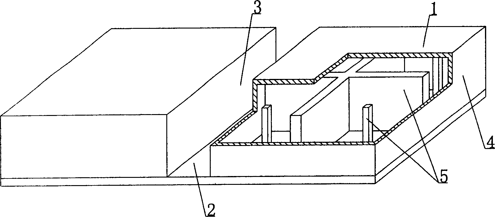
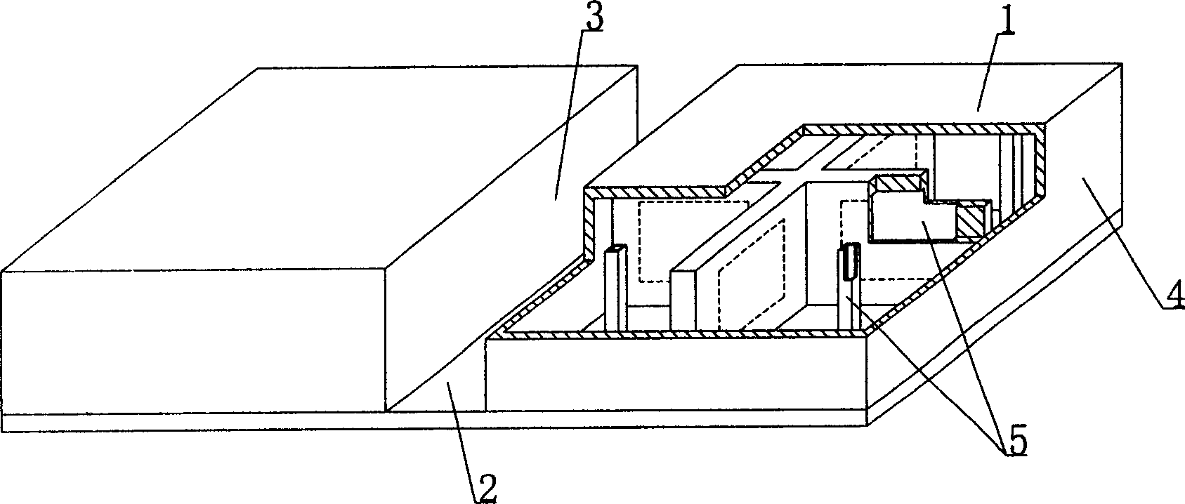
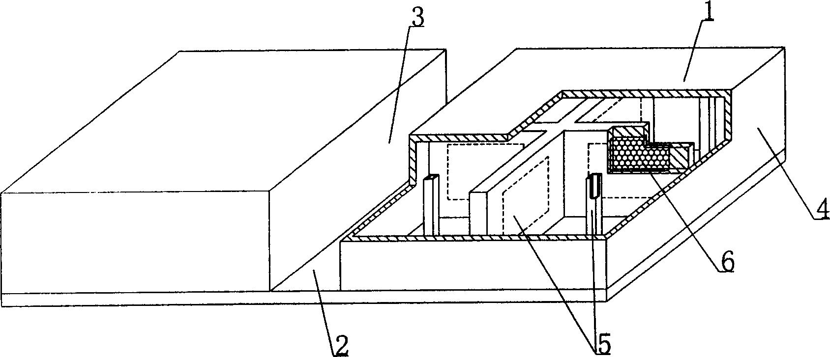
[0077] As shown in the drawings, the present invention includes a cavity mold shell 1 and a bottom plate 2. The cavity mold shell 1 and the bottom plate 2 are connected as a whole. On the bottom plate 2, there are at least two cavity mold shells 1 arranged alternately. 2 constitute at least one cast-in-place structure inner rib mold cavity 3, the other outer side of the cavity mold shell 1 constitutes the side template of the cast-in-place structure outer rib or beam or wall, characterized in that at least one cavity mold shell 1 is provided with At least one reinforcing member 5, the contact part of the cavity mold shell 1 and the bottom plate 2 is a groove 11, and the inner rib mold cavity 3 has at least two parallel bracing members 9. figure 1 It is a schematic diagram of the structure of Embodiment 1 of the present invention. In the drawings, 1 is a cavity mold she...


PUM


Abstract

The hollow cavity member includes cavity shutterings and a bottom slab connected integrally. On the bottom slab, there are at least two cavity shutterings arranged intermittently. The sides of the cavity and the bottom slab constitute in-situ cast mold cavity with at least one inner rib. The other sides of the cavity shuttering constitute the in-situ cast structure outer rib or the side formwork of the beam or wall. The hollow cavity member features that at least one of the cavity shutterings has at least one reinforcing part, the cavity shuttering has notch in the contact part to the bottom slab, and the inner rib mold cavity has at least two supporting parts. The present invention is suitable for in-situ cast or pre-stressed reinforced concrete hollow floor slab, roof, wall, foundation slab and hollow bridge.

Description

[0001] This application is a divisional application of the invention patent application whose application date is June 2, 2003, the application number is 03137262.7, and the name is "a cavity member". (1) Technical field [0002] The invention relates to a cavity member. (2) Background technology [0003] At present, most buildings with brick-concrete structure and reinforced concrete structure use prefabricated hollow slabs as floor slabs, which have the advantages of fast construction speed and low cost. However, because there is no firm connection between the two adjacent prefabricated hollow slabs, only cement mortar is used to fill the joints, so the integrity is poor, which is not conducive to earthquake resistance, and cracks and water seepage often occur. In order to solve the above problems, many buildings have adopted the method of cast-in-place concrete floor slabs (solid, hollow). Although the problems of earthquake resistance and cracking have been solved, a large num...

Claims


Application Information

Patent Timeline
Patent Type & Authority Applications(China)
IPC IPC(8): E04B5/18E04B5/36
Inventor 邱则有
Owner 湖南邱则有专利战略策划有限公司
Why Eureka
Try Eureka