Heat exchanger of air conditioner

The technology of a heat exchange device and an air conditioner is applied to the structural field of the heat exchange device and heat exchange equipment, which can solve the problems of excessively long defrosting time and incomplete defrosting, so as to reduce the amount of residual frost and improve the heat exchange efficiency. , the effect of reducing the defrosting time

Inactive Publication Date: 2004-12-08
LG ELECTRONICS (TIANJIN) APPLIANCES CO LTD
View PDF0 Cites 2 Cited by
  • Summary
  • Abstract
  • Description
  • Claims
  • Application Information

AI Technical Summary

Problems solved by technology

This time refers to the time when the surface of the outdoor heat exchanger has a sufficient amount of f

Method used


Image

  • Heat exchanger of air conditioner
  • Heat exchanger of air conditioner
  • Heat exchanger of air conditioner

Examples


Example Embodiment

[0024] The present invention will be described in detail below with reference to the drawings and embodiments.

[0025] The present invention can be applied to both indoor and outdoor heat exchangers of air conditioners. In the following, only embodiments applicable to outdoor heat exchangers are described.

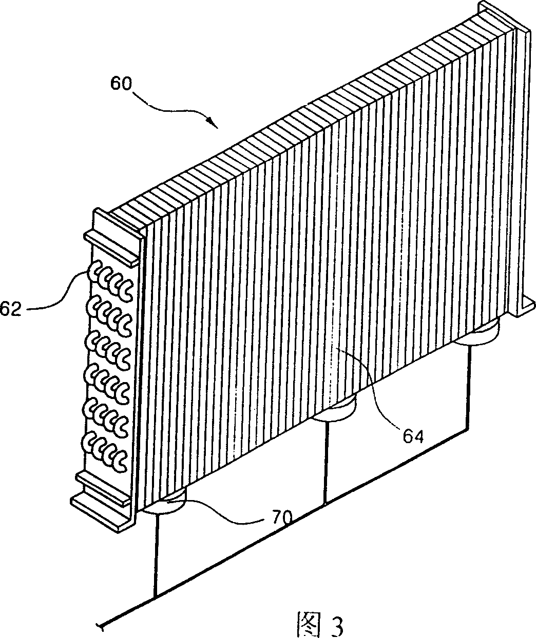
[0026] As shown in Fig. 3, the outdoor heat exchanger (60) is composed of a plurality of fluid tubes (62) and fins (64) vertically inserted around the fluid tubes (62). The outdoor heat exchanger (60) functions as a condenser during cooling and as an evaporator during heating.

[0027] Refrigerant flows inside the fluid pipe (62) constituting the outdoor heat exchanger (60), and the outdoor heat exchanger (60) performs heat exchange between the refrigerant inside the fluid pipe (72) and the outside air to achieve a cooling system. Hot purpose.

[0028] The fins (64) inserted vertically around the fluid pipe (62) guide the flow direction of the air, thereby expanding the heat ...


PUM


Abstract

The device sets multiple vibration motor under the outdoor heat exchanger of air conditioning to remove frosting at surface of outdoor heat exchanger and hydrophobic material is applied to manufacture fins for outdoor heat exchanger so as to decrease frosting amount at surface of outdoor heat exchanger.

Description

technical field [0001] The present invention relates to the arrangement of the defrosting device of the heat exchanger of the air conditioner, or the structure of the heat exchange equipment characterized by the selection of specific materials. Specifically, it is a heat exchange device of an air conditioner. Background technique [0002] Such as figure 1 , 2, the refrigerant circulating in the heat exchanger of the air conditioner is compressed by the compressor (10) and flows into the indoor heat exchanger (20). The indoor heat exchanger (20) exchanges heat between the refrigerant and the indoor air. Then, the refrigerant that has passed through the indoor heat exchanger (20) is decompressed in the expansion tube (30) and then flows into the outdoor heat exchanger (40) to exchange heat with the outdoor air. [0003] The cold and hot air conditioner is provided with the indoor heat exchanger (20) and the outdoor heat exchanger (40) selectively supplying the refrigerant c...

Claims


Application Information

Patent Timeline
IPC IPC(8): F24F13/30
Inventor 金容珍
Owner LG ELECTRONICS (TIANJIN) APPLIANCES CO LTD
Why Eureka
Try Eureka