Air conditioner
A technology for air conditioning and outdoor heat exchangers, applied in the direction of compressors with reversible cycles, compressors, damage protection, etc., can solve the problems of reducing refrigerant speed, refrigerant noise, increasing the diameter of pipes, etc. The effect of shortened time, high reliability and safe power-on
- Summary
- Abstract
- Description
- Claims
- Application Information
AI Technical Summary
Problems solved by technology
Method used
Image
Examples
Embodiment approach 1
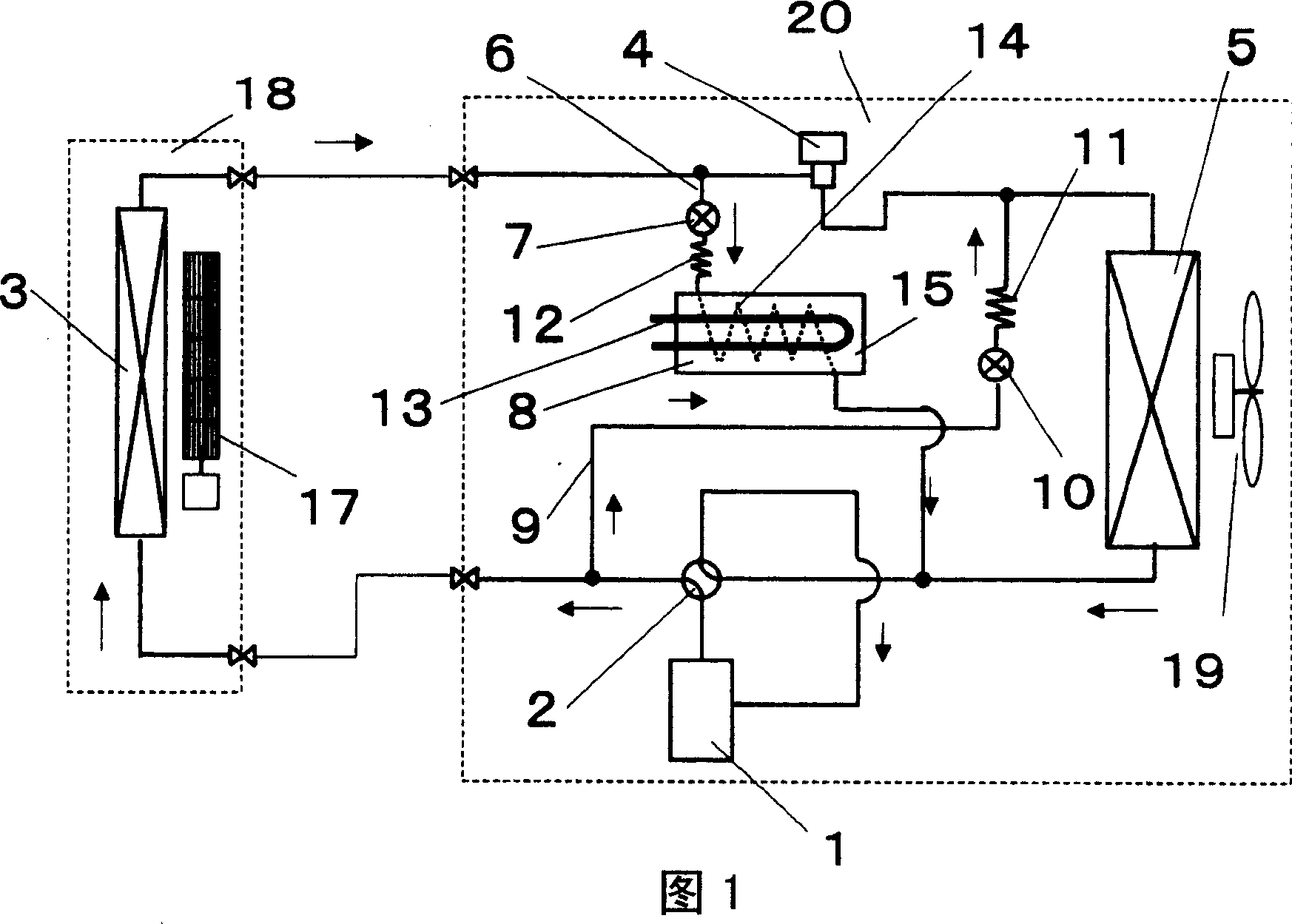
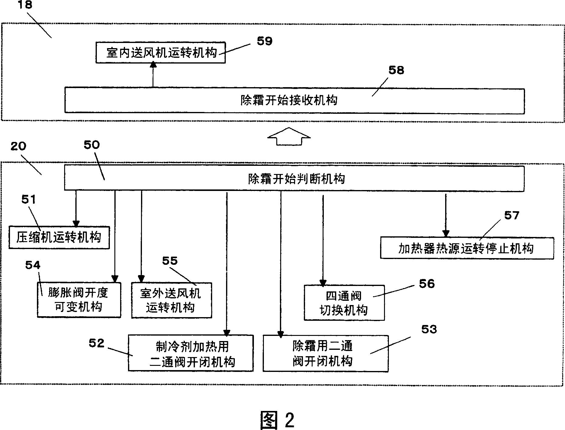
[0059] FIG. 1 shows a block diagram of an air-conditioning apparatus according to Embodiment 1 of the present invention.
[0060] In FIG. 1 , an outdoor unit 20 includes a compressor 1 , a four-way valve 2 , a pressure reducer 4 , an outdoor heat exchanger 5 , and an outdoor blower 19 . The pressure reducer 4 here can also be an electromagnetic expansion valve. On the other hand, the indoor unit 18 includes the indoor heat exchanger 3 and the indoor blower 17 .
[0061] In addition, the outdoor unit 20 is provided with a first bypass circuit 6 and a second bypass circuit 9 . The first bypass circuit 6 connects the piping between the indoor heat exchanger 3 and the pressure reducer 4, and the piping between the four-way valve 2 and the outdoor heat exchanger 5, and has a two-way valve 7 for refrigerant heating, a refrigerant Heater 8. Further, the refrigerant heater 8 includes a pressure reducer 12 for refrigerant heating, a refrigerant heating heat source 13, a refrigerant ...
Embodiment approach 2
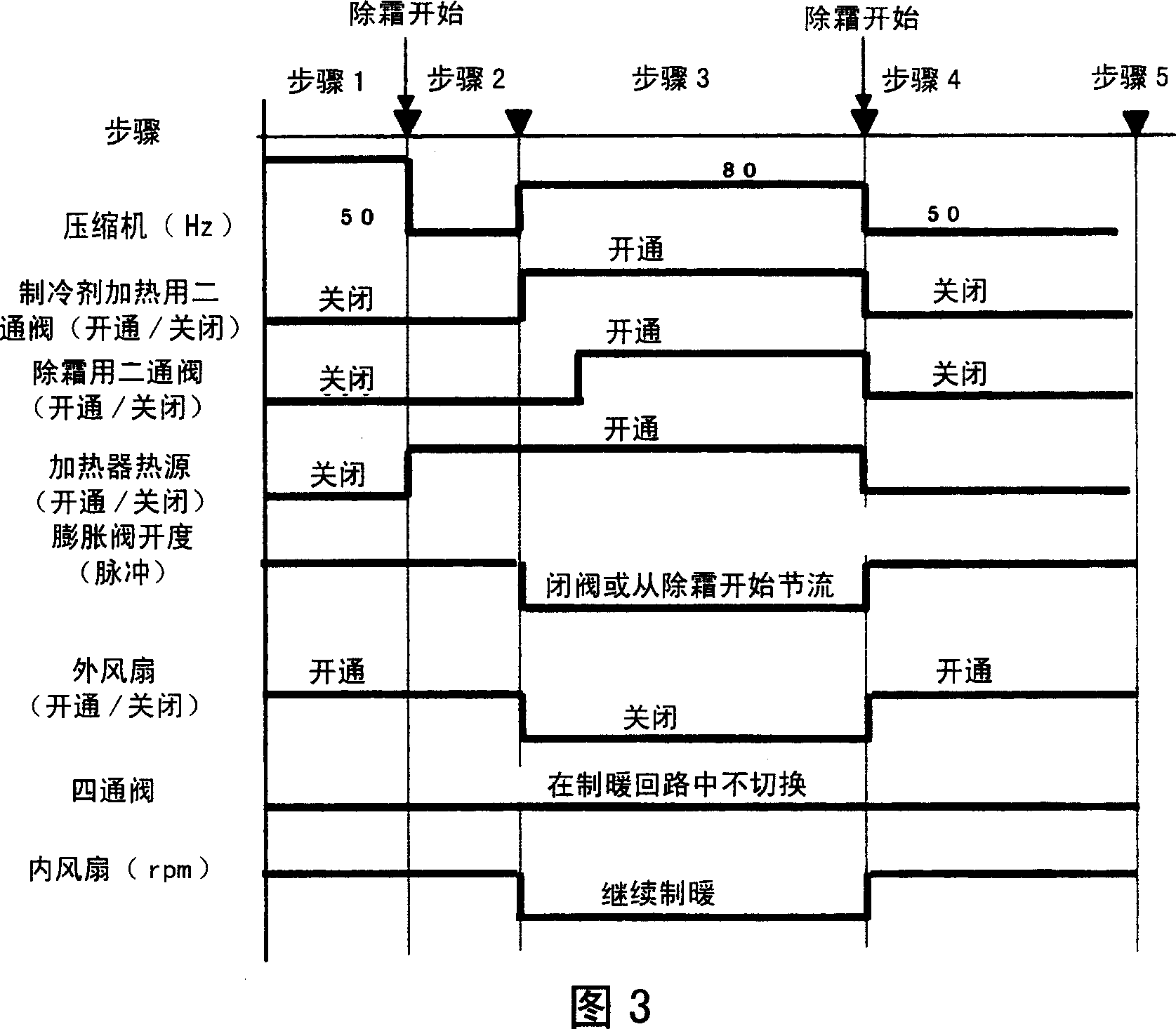
[0075] FIG. 4 is a timing chart when the control of Embodiment 2 of the present invention operates, and the configuration diagram and control block diagram of the air-conditioning apparatus are the same as those of Embodiment 1 described above.
[0076] As shown in FIG. 4 , when it is judged to start defrosting, the heating operation by the heat pump in step 1 is performed to the preparatory operation in step 2 before turning on the refrigerant heating heat source 13 of the refrigerant heater 8 . In this preparatory operation, the frequency of the compressor 1 is reduced by changing the current control value in a decreasing direction to reduce the integrated current value until the current capacity does not exceed the standard, and the refrigerant heating heat source 13 can be safely turned on.
[0077] Next, in step 3, the current control value is increased, and the refrigerant heating heat source 13 is turned on. In addition, the frequency of the compressor is then increased...
Embodiment approach 3
[0080] FIG. 5 is a time chart when the control in Embodiment 3 of the present invention operates, and the configuration diagram and control block diagram of the air-conditioning apparatus are the same as those in Embodiment 1 described above.
[0081] As shown in FIG. 5 , when it is determined to start defrosting, the heating operation by the heat pump in step 1 is shifted to the heating operation by the refrigerant heating operation in step 2 .
[0082] First, the two-way valve 7 for refrigerant heating is opened to control in the opening direction, and the refrigerant heating heat source 13 is also turned on to perform the refrigerant heating operation. At this time, the pressure reducer 4 such as an expansion valve performs a closed operation or a nearly closed operation.
[0083] Therefore, most of the refrigerant condensed by the indoor heat exchanger 3 flows into the first bypass circuit 6, passes through the two-way valve 7 for refrigerant heating, the pressure reducer ...
PUM
 Abstract
Description
Claims
Application Information
 - R&D
- Intellectual Property
- Life Sciences
- Materials
- Tech Scout
- Unparalleled Data Quality
- Higher Quality Content
- 60% Fewer Hallucinations
Browse by: Latest US Patents, China's latest patents, Technical Efficacy Thesaurus, Application Domain, Technology Topic, Popular Technical Reports.
© 2025 PatSnap. All rights reserved.Legal|Privacy policy|Modern Slavery Act Transparency Statement|Sitemap|About US| Contact US: help@patsnap.com


