Multiple light source lighting system for projector

A lighting system and multi-light source technology, applied in the field of optical lighting, to achieve the effect of low technical requirements

Inactive Publication Date: 2004-12-15
SHANGHAI JIAO TONG UNIV
View PDF6 Cites 22 Cited by
  • Summary
  • Abstract
  • Description
  • Claims
  • Application Information

AI Technical Summary

Problems solved by technology

[0016] 3. If the micro-display panel is a liquid crystal panel, in addition to meeting the uniformity requirements for the lighting system, it must also convert the lighting light into polarized light

Method used


Image

  • Multiple light source lighting system for projector
  • Multiple light source lighting system for projector
  • Multiple light source lighting system for projector

Examples


Embodiment Construction

[0044] The technical solution of the present invention will be further described below in conjunction with the accompanying drawings.

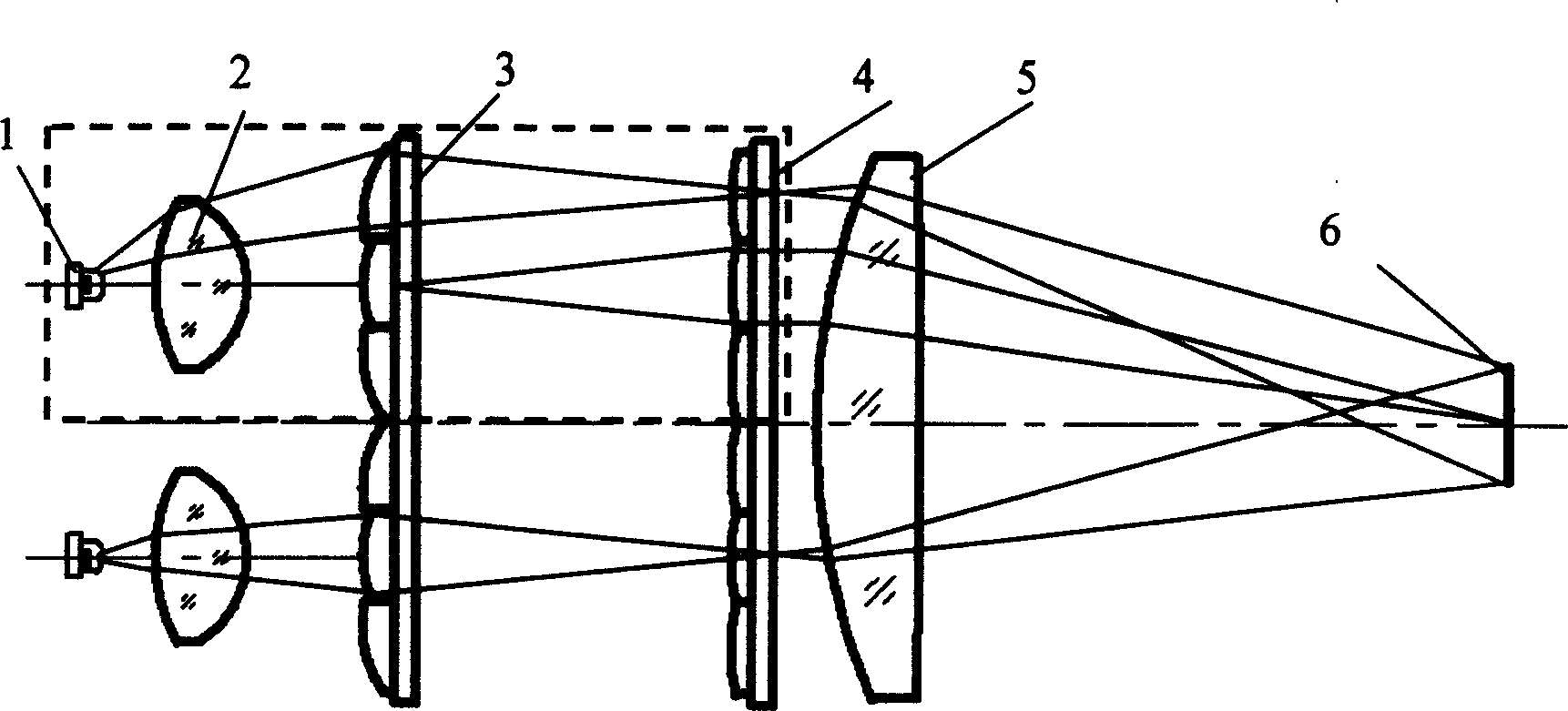
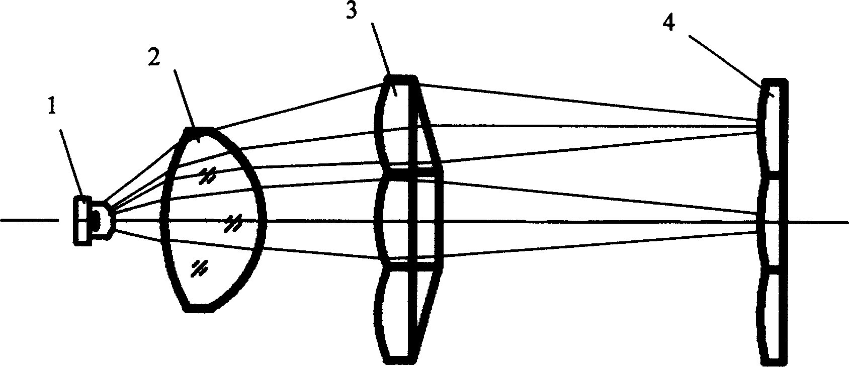
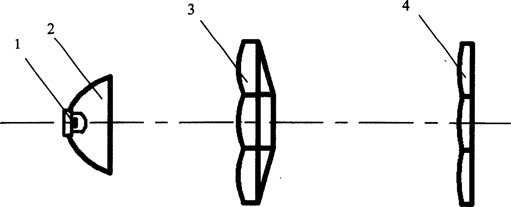
[0045] figure 1 Shown is a schematic structural composition of an embodiment of the multi-light source lighting system of the present invention. Within the range of the dotted line in the figure is a lighting unit, which is composed of a light emitting diode 1 , a collimating mirror 2 , a first fly's eye lens 3 and a second fly's eye lens 4 to form a lighting unit. The lighting units are placed side by side, wherein the first fly-eye lenses 3 are placed side by side to form a first fly-eye lens group, and the second fly-eye lenses 4 are placed side by side to form a second fly-eye lens group. A converging lens 5 is placed in the beam outgoing direction of the group, and several lighting units and a converging lens 5 constitute the multi-light source lighting system of the present invention. The object to be illuminated - the microdisplay pan...


PUM


Abstract

The multiple light source lighting system for projector consists of one or several lighting units comprising one LED, one collimating lens and two fly lenses, and one converging lens. Each of the two fly lenses consists of several rectangular lenses. Light the LENs emit is divergence angle compressed in the collimating lens to form collimated light beam, the collimated light beam is cut in the first fly lens into fine light beams in the number of rectangular lenses and converged to near the second fly lens, the light beams through the second fly lens are converged onto the micro display panel. The present invention has low system heat dissipation requirement, long light source life, high color balance and high color vividness.

Description

Technical field: [0001] The invention relates to a multi-light source lighting system for a projector, which is used for providing lighting to a micro display panel of the projector. It belongs to the technical field of optical lighting. Background technique: [0002] Projectors currently mainly include liquid crystal (LCD——Liquid Crystal Display) projectors, liquid crystal on silicon (LCOS——Liquid Crystal on Silicon) projectors, and digital light processor (DLP——Digital Light Processor) projectors. The principle is to use an illumination system to provide suitable illumination for the micro-display panel, add an image signal to the micro-display panel, and finally project the image on the micro-display panel onto the screen by the illumination system. [0003] In the prior art, LCD projectors and LCOS projectors usually use a gas discharge lamp (such as a high-pressure mercury lamp or a xenon lamp, etc.) The polarizing beam splitter (PBS—Polarization Beam Splitter) array ...

Claims


Application Information

Patent Timeline
Patent Type & Authority Applications(China)
IPC IPC(8): G02B3/00G03B21/14G03B21/20
Inventor 王蔚生藤森知雄窦晓鸣黄维实
Owner SHANGHAI JIAO TONG UNIV
Why Eureka
Try Eureka