Signal encoding device, method, signal decoding device, and method

A signal coding and encoding technology, applied in code conversion, electrical components, voice analysis, etc., can solve the problem of no tone analysis

Inactive Publication Date: 2005-02-09
SONY CORP
View PDF0 Cites 11 Cited by
  • Summary
  • Abstract
  • Description
  • Claims
  • Application Information

AI Technical Summary

Problems solved by technology

Since there are extremely few tones in the case of voice (voice) for telephone use, and most of them will contain multiple tones in general sound signals, it is ineffective to use such a method, and in many occasions there is no tone analysis at all. Function

Method used


Image

  • Signal encoding device, method, signal decoding device, and method
  • Signal encoding device, method, signal decoding device, and method
  • Signal encoding device, method, signal decoding device, and method

Examples


Embodiment Construction

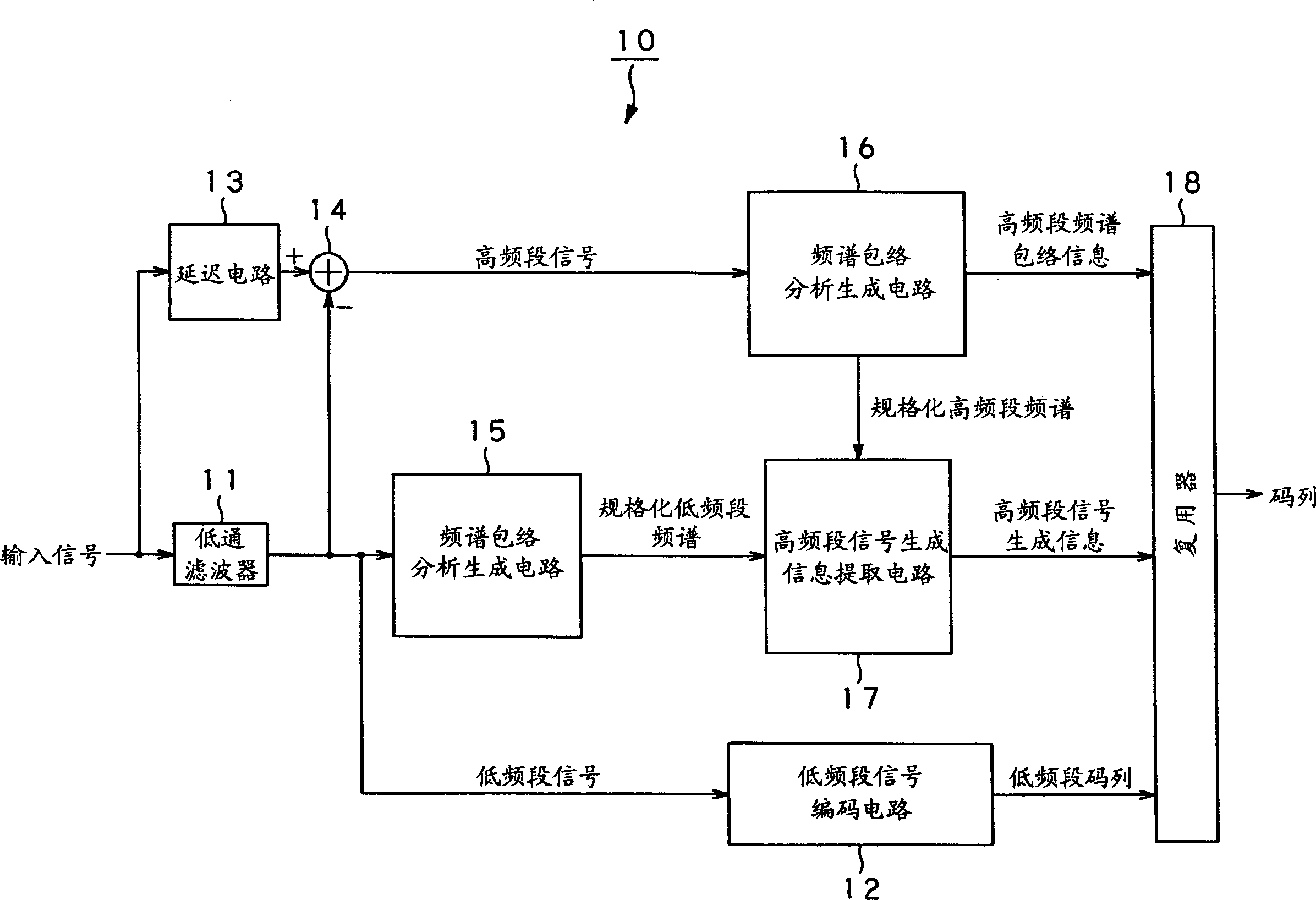
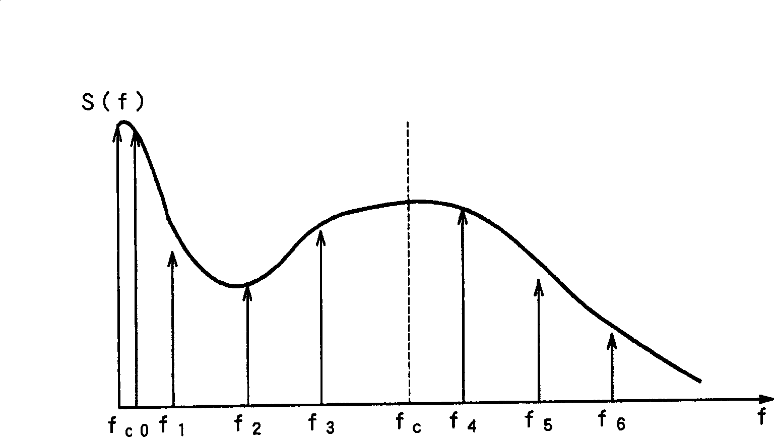
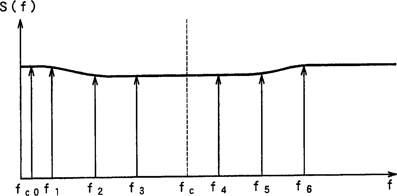
[0032] Hereinafter, specific embodiments to which the present invention is applied will be described in detail with reference to the drawings. In this implementation, the example of the present invention is applicable to a signal encoding device and method for restricting the input timing signal to a low frequency band (low frequency band signal), and uses the image of the low frequency spectrum on the frequency axis, such as aliasing. Or a signal decoding device and method for shifting (parallel moving) to expand the timing signal to a high frequency band (high frequency band signal).

[0033] Simply put, in this embodiment, the input timing signal is limited to have a cutoff frequency f on the encoding side c Or below the cutoff frequency f c At the same time as the low-frequency signal, adaptively determine the aliasing frequency f used for the generation of the high-frequency signal on the decoding side a Or shift frequency f sh Wait. Moreover, on the decoding side, the low-fr...


PUM


Abstract

A signal encoding apparatus (10) limits an inputted time series signal to a low frequency band signal having a certain cut-off frequency or less to include the low frequency band signal into code train for outputting encoded low frequency band code train. In addition, the signal encoding apparatus (10) adaptively determines aliasing frequency fa, shift frequency fsh or tone.noise synthesis information r used for generation of high frequency band signal at the decoding side to include these information into code train outputted along with high frequency band spectrum envelope information as high frequency band generation information. A signal decoding apparatus generates a high frequency band signal from a low frequency band signal by using high frequency band signal generation information included in code train and high frequency band spectrum envelope to add the generated high frequency band signal and the low frequency band signal to thereby output a time series signal extended up to the high frequency band signal.

Description

Technical field [0001] The present invention relates to a signal encoding device and method, a signal decoding device and method, a program, and a recording medium that are suitable when a time series signal limited to a frequency band on the encoding side is expanded to a signal in a wider frequency band on the decoding side. Background technique [0002] In recent years, in the high-efficiency encoding of audio signals, the mechanism of human hearing can be used to compress the sound quality equivalent to CD (music compact disc) to about 1 / 10 of the data volume of the original CD. Now, commodities using these technologies have been circulated in the market, and it has been possible to record sound signals on smaller recording media and / or distribute (transmit) them through the network. [0003] In such high-efficiency compression, separate formats are used. If the corresponding format is within the range of the format, it is possible to freely control the sound quality and code...

Claims


Application Information

Patent Timeline
Patent Type & Authority Applications(China)
IPC IPC(8): G10L19/02H03M7/30
CPCG10L19/0204G10L21/038H03M7/30G10L19/02
Inventor 本间弘幸松本淳
Owner SONY CORP
Why Eureka
Try Eureka