Servo-assisted butterfly valve provided with a compression spring to stabilise the limp-home positions

A technology of butterfly valve and elastic body, which is applied in the direction of lifting valve, valve device, electrical control, etc., and can solve the problem of changing the inelastic in-situ air flow value, etc.

Inactive Publication Date: 2005-02-23
FAB ITAL MAGNETI MARELLI SPA
View PDF0 Cites 2 Cited by
  • Summary
  • Abstract
  • Description
  • Claims
  • Application Information

AI Technical Summary

Problems solved by technology

[0006] However, even with such bolts, it is not possible to significantly change the value of the air flow in the inelastic in-situ without changing the mold

Method used


Image

  • Servo-assisted butterfly valve provided with a compression spring to stabilise the limp-home positions
  • Servo-assisted butterfly valve provided with a compression spring to stabilise the limp-home positions
  • Servo-assisted butterfly valve provided with a compression spring to stabilise the limp-home positions

Examples


Embodiment Construction

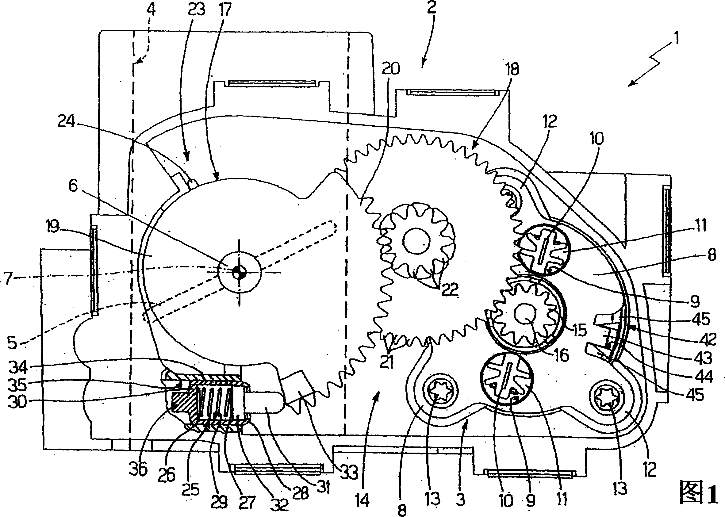
[0016] In Figure 1, a servo-assisted butterfly valve for an internal combustion engine is indicated generally by 1; the butterfly valve 1 comprises a valve body 2 housing an electric actuator 3, a cylindrical valve seat 4 (in the figure Schematically represented by a dotted line) and a butterfly body 5 that engages the valve seat 4 and moves between the maximum open position and the closed position of the valve seat 4 under the action of the electric actuator 3 (schematically represented by a dotted line in the figure ). The butterfly body 5 is key-fitted on a metal shaft 6 mounted on the valve body 2 for rotation about a longitudinal axis 7 under the action of an electric actuator 3 in the aforementioned maximum open position and the aforementioned closed position of the valve seat 4 Move the butterfly body 5 between.

[0017] The electric actuator 3 consists of a cylinder which is inserted into a corresponding cylindrical seat on the valve body 2 and held in place in the cy...


PUM


Abstract

A butterfly valve comprising a valve seat, a butterfly body engaging the valve seat, a shaft on which the butterfly body is keyed, an electric actuator coupled to the shaft, a torsional return spring adapted to rotate the butterfly body towards a closed position, a compression abutment spring adapted to rotate the butterfly body towards an open position, and an abutment body which causes the action of the abutment spring to stop when the butterfly body is in a limp-home position; the abutment spring having a mechanically fixed end connected to the valve body and a mechanically moving end connected to a wheel rigid with the shaft by means of the interposition of a transmission member mounted to slide within a chamber housing the abutment spring.

Description

technical field [0001] The invention relates to a servo-assisted butterfly valve for an internal combustion engine. Background technique [0002] In internal combustion engines, the function of butterfly valves is to regulate the flow of fresh air supplied to the cylinders. The known type of butterfly valve consists of a valve body housing a valve seat engaged by a butterfly body keyed on a shaft for movement under the action of an electric actuator connected to the shaft by a gear transmission. Rotate between maximum open position and closed position. A torsional return spring acts on the shaft (i.e. the spring deforms to produce a circular displacement producing a resistive moment), the return spring is coaxially mounted on the shaft and is mechanically connected to the shaft to apply a torque on the shaft which causes the shaft to into the closed position. The shaft is also acted upon by a torsional reaction spring mounted coaxially on the shaft to exert a torque on th...

Claims


Application Information

Patent Timeline
Patent Type & Authority Applications(China)
IPC IPC(8): F02D11/10
CPCF02D11/10F02D2041/227F02D11/107
Inventor 萨尔瓦托雷·武特拉库达卢恰诺·伊索皮多梅尼科·坎诺内
Owner FAB ITAL MAGNETI MARELLI SPA
Why Eureka
Try Eureka