Computer with scanning function and method for generating model

A computer and functional technology, applied in the field of computer and model generation, can solve the problems of high price, not clear image, distortion, etc., and achieve the effect of simple and cheap equipment and clear image

Active Publication Date: 2019-10-15
上海青燕和示科技有限公司
View PDF10 Cites 0 Cited by
  • Summary
  • Abstract
  • Description
  • Claims
  • Application Information

AI Technical Summary

Problems solved by technology

[0006] The technical problem to be solved by the present invention is to overcome the defects that 3D cameras in the prior art are expensive, often appear to be distorted, and the images are not clear enough, and provide a convenient and quick way to acquire 3D models.

Method used


Image

  • Computer with scanning function and method for generating model
  • Computer with scanning function and method for generating model

Examples


Embodiment 1

[0036] see figure 1 , the present embodiment provides a computer with a scanning function, and the scanning function is a function of creating a 3D model after scanning an object or a portrait.

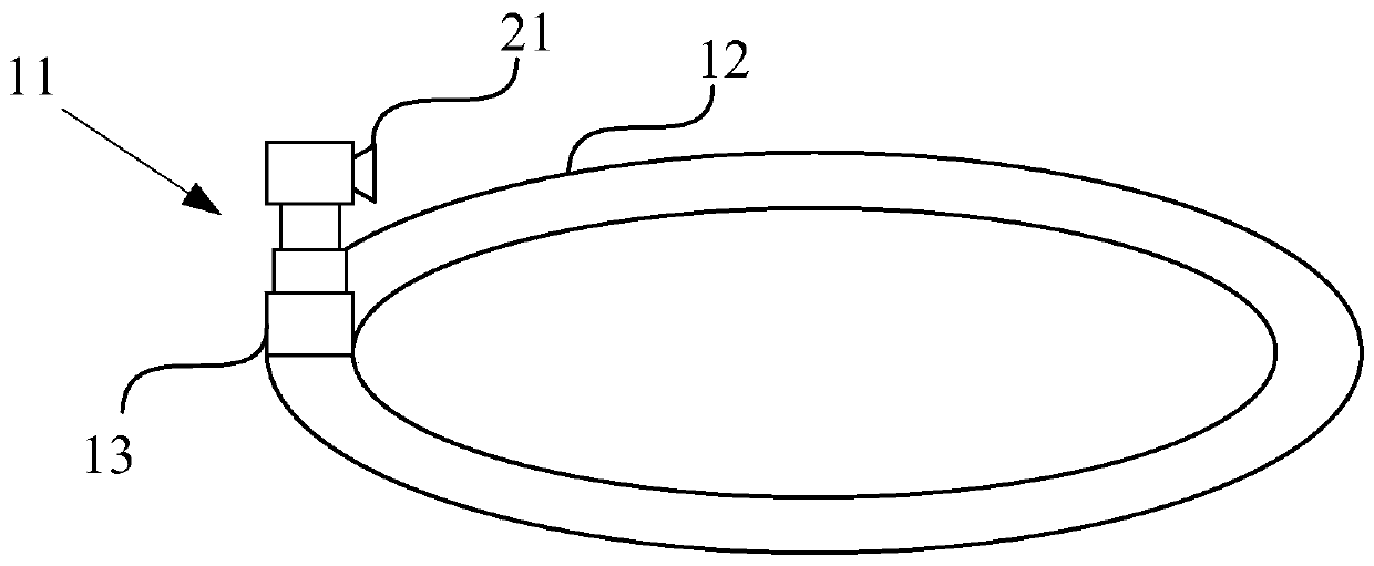
[0037] The computer includes a processor, a 3D lens 21 and a lens supporting device.

[0038] The 3D lens includes an infrared beam emitter, an infrared receiver and a camera, the infrared beam emitter and the infrared receiver are used to generate the structural layer of the 3D image, and the camera is used to generate the 3D image pixel layer.

[0039] The lens supporting device 11 includes a circular slide rail 12 and a support frame 13 for sliding on the circular slide rail. The height of the support frame is adjustable.

[0040] The support frame is used to support and fix the 3D lens.

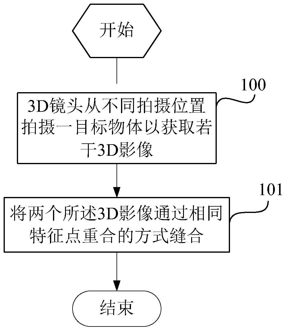
[0041] The 3D lens is used to shoot a target object in the circular slide rail from different shooting positions on the support frame to obtain several 3D images, and the 3D images correspond ...

Embodiment 2

[0054] This embodiment is basically the same as Embodiment 1, the only difference is:

[0055] The computer of this embodiment can also realize a specific image stitching function:

[0056] For a target 3D image, the processor is used to select a feature point in the target 3D image, and obtain the distance from the feature point to the axis of the circular slide rail and the target angle, wherein the target angle is the feature point The angle between the line connecting the projection point of the axis and the 3D lens and the plane where the axis is located, the axis is a straight line passing through the center of the circular slide rail and perpendicular to the plane where the circular slide rail is located;

[0057] The processor is also used to determine the next 3D image in the next 3D image of the target 3D image by using the rotation angle of the support frame, the distance from the feature point to the axis, and the target angle. The location of the feature points, ...

Embodiment 3

[0065] This embodiment is basically the same as Embodiment 1, the only difference is:

[0066] Each 3D image includes a pixel layer and a structure layer, and for 3D images corresponding to any two adjacent shooting positions, the processor is used to identify at least 3 peak points on the structure layers of the two 3D images;

[0067] The processor is also used to sew the structural layers of the two 3D images by overlapping the same peak points, the peak points include convex points and concave points, and the peak points of the two 3D images overlap by at least There are three, and two pixel layers of the 3D image are pasted on the stitched 3D image.

[0068] Using the computer of this embodiment, the stitching method in the model generation method of this embodiment specifically includes:

[0069] identifying at least 3 peak points on the structural layers of both said 3D images;

[0070] Stitching the structural layers of the two 3D images by overlapping the same peak ...


PUM


Abstract

The invention discloses a computer having a scanning function and a model generation method. The computer comprises a processor, a 3D lens and a lens support device; the lens support device comprisesa circular slide rail and a support frame used for sliding on the circular slide rail; the support frame is used for supporting and fixing the 3D lens; the 3D lens is used for shooting a target objectin the circular slide rail on the support frame from different shooting positions, so that a plurality of 3D images are obtained; the 3D images and the shooting positions are in one-to-one correspondence; for the 3D images respectively corresponding to any two adjacent shooting positions, the processor is used for identifying feature points on the two 3D images; and the two 3D images are stitchedin a manner of overlapping the same feature points. According to the computer having the scanning function and the model generation method disclosed by the invention, the 3D model can be obtained; furthermore, the process is convenient and rapid; images are relatively clear; and the implementation device is simple and cheap.

Description

technical field [0001] The invention relates to a computer with scanning function and a model generation method. Background technique [0002] A 3D camera is a camera made with a 3D lens. It usually has more than two camera lenses with a distance close to that of the human eye, and can capture different images of the same scene similar to what the human eye sees. Holographic 3D has more than 5 lenses on the disk, and the same image can be viewed in all directions through dot grating imaging or rhombus grating holographic imaging, as if you are on the scene. [0003] The first 3D camera So far the 3D revolution has all revolved around Hollywood blockbusters and major sports events. With the advent of 3D cameras, this technology is one step closer to home users. After the launch of this camera, we will be able to use 3D lenses to capture every memorable moment in life, such as a child's first step, college graduation celebration and so on. [0004] 3D cameras usually have m...

Claims


Application Information

Patent Timeline
Patent Type & Authority Patents(China)
IPC IPC(8): H04N13/204H04N13/275G06T17/00
Inventor 戴佑俊
Owner 上海青燕和示科技有限公司
Why Eureka
Try Eureka