X-ray inspection apparatus and X-ray inspection method

a technology of x-ray inspection and x-ray inspection, which is applied in the direction of material analysis using wave/particle radiation, instruments, applications, etc., can solve the problems of difficult to view the condition of each component accurately, difficult to view the detailed condition of each component, and the limitation of the magnifying factor, so as to achieve the accurate acquisition of information on the desired cross section, high resolution, and high density packaging

Inactive Publication Date: 2005-04-07
PANASONIC CORP
View PDF4 Cites 57 Cited by
  • Summary
  • Abstract
  • Description
  • Claims
  • Application Information

AI Technical Summary

Benefits of technology

[0018] The present invention intends to solve the problems of the conventional various X-ray inspection devices and to provide an X-ray inspection device and an X-ray inspection method capable of acquiring information on a desired cross section accurately even when an interval between components of an object to be inspected becomes narrower, resulting in high density p

Problems solved by technology

However, in the case that a plurality of components are packaged with being overlapped with each other, the components overlap each other in an X-ray image and therefore it is difficult to view the condition of each component accurately.
For this reason, the conventional X-ray inspection device shown in FIG. 18 has a problem that it is difficult to view a detailed condition of each component.
For this reason, there causes a problem that even when the user ties to magnify the X-ray image by moving the object to be inspected 102 closer to the r

Method used


Image

  • X-ray inspection apparatus and X-ray inspection method
  • X-ray inspection apparatus and X-ray inspection method
  • X-ray inspection apparatus and X-ray inspection method

Examples


first embodiment

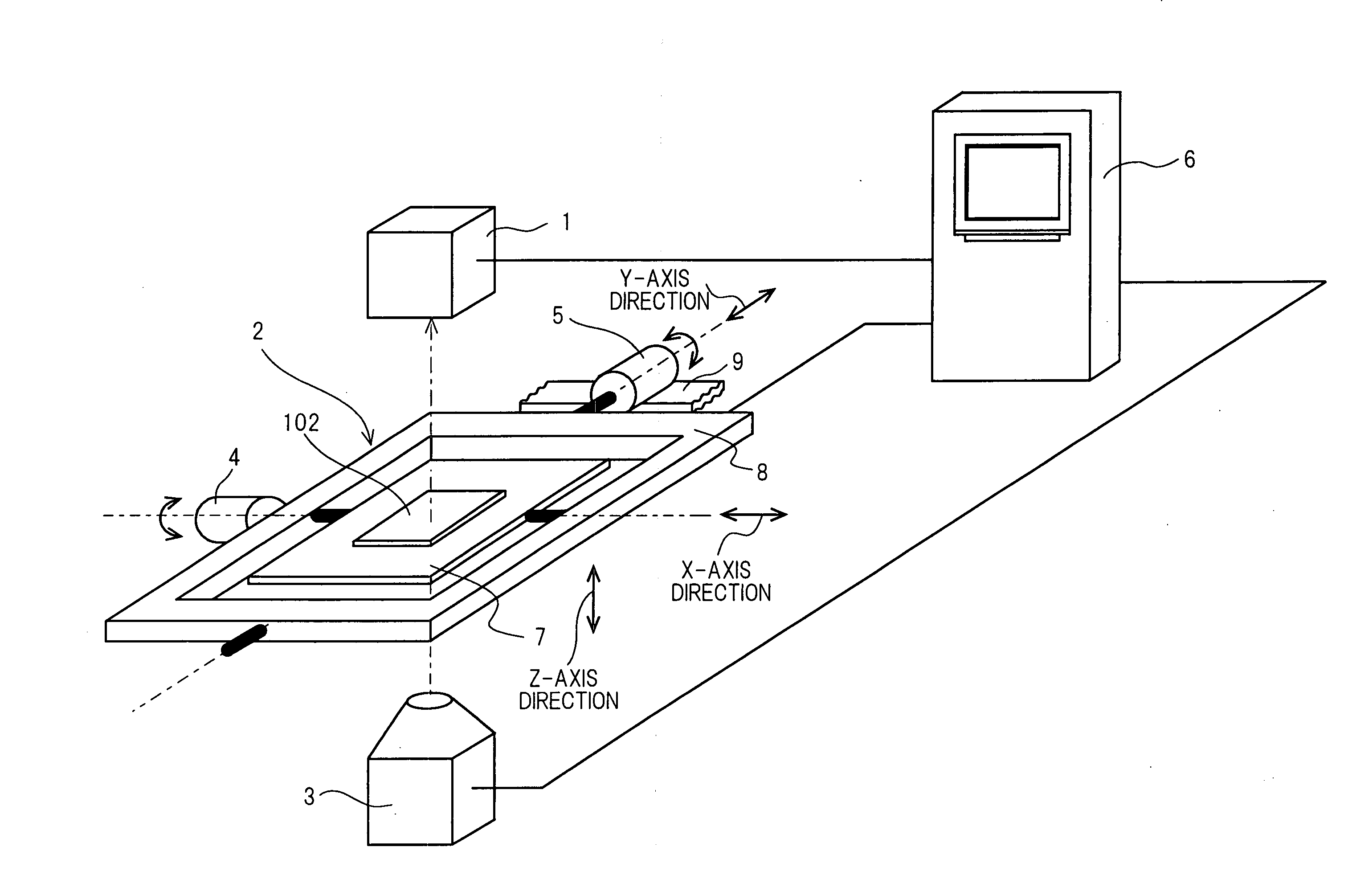
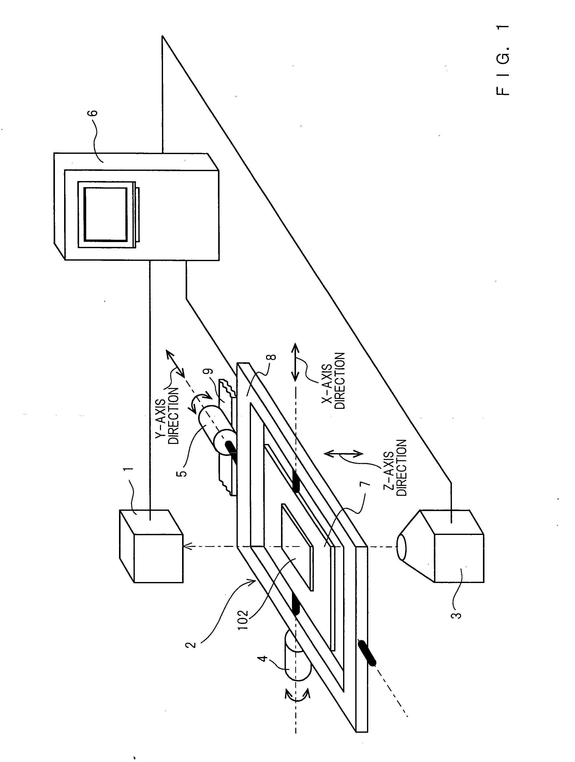
[0080]FIG. 1 is a view showing a schematic configuration of an X-ray inspection device in accordance with the present invention.

[0081] As shown in FIG. 1, an X-ray radiated from an X-ray irradiation device 3 is irradiated to an object to be inspected 102 held by a swinging device 2, for example, a circuit forming body including a printed circuit board and so on, and the X-ray that passes through the object to be inspected 102 is detected by an X-ray detection device 1. The X-ray irradiation device 3 is located on the extension line connecting the center of the swinging device 2 and the imaging central position of the X-ray detection device 1 (X-ray path) and emits the X-ray toward the X-ray detection device 1. A control device 6 controls transfer of the swinging device 2 in the Z-axis direction (direction of an X-ray irradiation axis) and tilt angles with respect to the X axis and Y axis of the swinging device 2 as well as controls driving of the X-ray detection device 1 and the X-r...

second embodiment

[0107] As shown in FIG. 9, also in the X-ray inspection device of the second embodiment, the X-ray radiated from the X-ray irradiated device 3 is irradiated to the object to be inspected 102 held by the swinging device 2 and the X-ray that passes through the object to be inspected 102 is detected by the X-ray detection device 1. The X-ray focus (spot position) of the X-ray irradiation device 3 is located on the direct extension of the center of the swinging device 2 and the imaging center position of the X-ray detection device 1 and emits the X-ray toward the X-ray detection device 1.

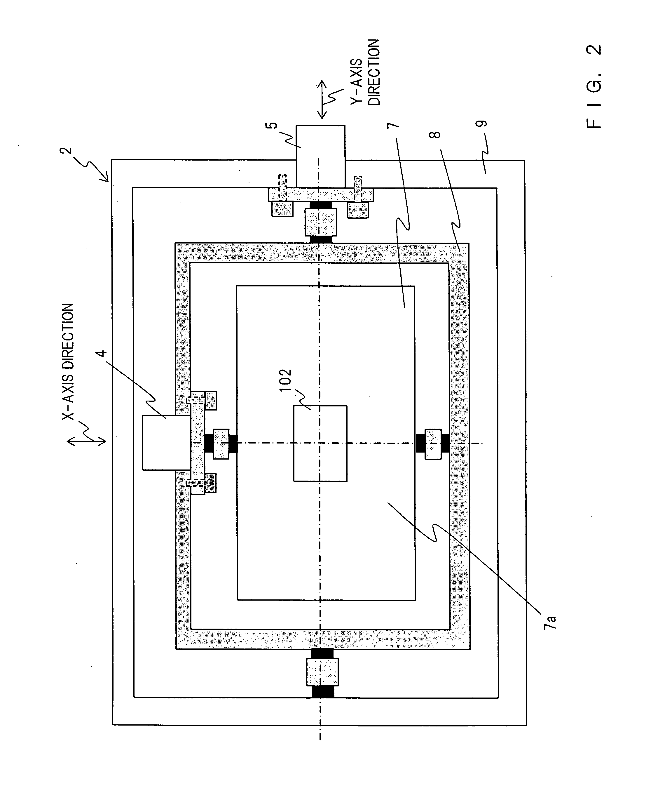
[0108] In the X-ray inspection device of the second embodiment, as shown in FIG. 10, a multi-axial control device 25 as a driving mechanism of the object to be inspected is provided on the XY stage 7 of the swinging device 2. This multi-axial control device 25 is not shown in FIG. 9. In the X-ray inspection device of the second embodiment, the XVZ transfer table 26 on the XY stage 7 is configured so as ...

third embodiment

[0123] Further, as in a third embodiment, it may be configured that the swinging device 20 for X-ray detection and the X-ray irradiation device 3 is provided with a driving mechanism so as to transfer the swinging device 20 for X-ray detection and the X-ray irradiation device 3 in the direction of X-ray irradiation axis (Z-axis direction) simultaneously or separately, thereby enabling the magnifying factor of the X-ray image to be set greater.

[0124]>

[0125]FIG. 12 is a plan cross-sectional view showing a main internal configuration of an X-ray inspection device in accordance with a third embodiment of the present invention and FIG. 13 is a front cross-sectional view thereof. FIG. 14 to FIG. 17 are explanation views of radiography and image synthesis in the X-ray inspection device in accordance with the third embodiment. The same reference numerals are given to elements of the third embodiment having the same function and configuration as those of the first and second embodiments and ...


PUM


Abstract

The X-ray inspection device and the X-ray inspection method according to the present invention are configured to hold an object to be inspected irradiated with an X-ray from an X-ray irradiation device, uses a swinging device for performing swinging motion of tilting the object to be inspected at an arbitrary angle and in an arbitrary direction, images the X-ray that passes through the object to be inspected in an X-ray detection device and extracts data of a desired cross section from the X-ray image of the X-ray detection device in a control device.

Description

BACKGROUND OF THE INVENTION [0001] The present invention relates to an X-ray inspection device, for example, an X-ray inspection device and an X-ray inspection method that inspect the bonding condition of a component mounted on a printed circuit board, the bonding condition of the inside of a component packaged with resin or metal and the bonding condition of a component packaged within a printed circuit board. [0002] In these years, devices such as PDA [personal digital assistant] have been miniaturized and upgraded, and in packaging electronic components in the devices, to package as many electronic components as possible in small space, increase in packaging density, face-down bonding of bonding an electrode provided on a lower face of the electronic components to a land of a printed circuit board, and built-in of electronic components of packaging the electronic components within a printed circuit board have been promoted. [0003] Since a bonded part by the above-mentioned face-d...

Claims


Application Information

Patent Timeline
IPC IPC(8): G01B15/06G01N23/02A61B6/00G01N23/04H05G1/02H05G1/08H05G1/26
CPCG01N2223/419G01N23/046G01N2223/6113A61B6/00
Inventor ICHIHARA, MASARUYOSHINO, SHINJIINOUE, HIROYUKIKINOSHITA, TOSHIOOHUCHI, KAZUO
Owner PANASONIC CORP
Why Eureka
Try Eureka