Controller for synchromotor, electric equipment and module

A technology of synchronous motor and control device, applied in the direction of motor control, motor generator control, AC motor control, etc., can solve the problems of vibration and noise, difficulty of synchronous motor, etc., and achieve the effect of suppressing vibration and noise

Inactive Publication Date: 2005-07-13
HITACHI JOHNSON CONTROLS AIR CONDITIONING INC
View PDF6 Cites 16 Cited by
  • Summary
  • Abstract
  • Description
  • Claims
  • Application Information

AI Technical Summary

Problems solved by technology

Therefore, if the rotation pulsation is further increased, the problem of vibration and noise cannot be solved

Method used


Image

  • Controller for synchromotor, electric equipment and module
  • Controller for synchromotor, electric equipment and module
  • Controller for synchromotor, electric equipment and module

Examples


Embodiment 1

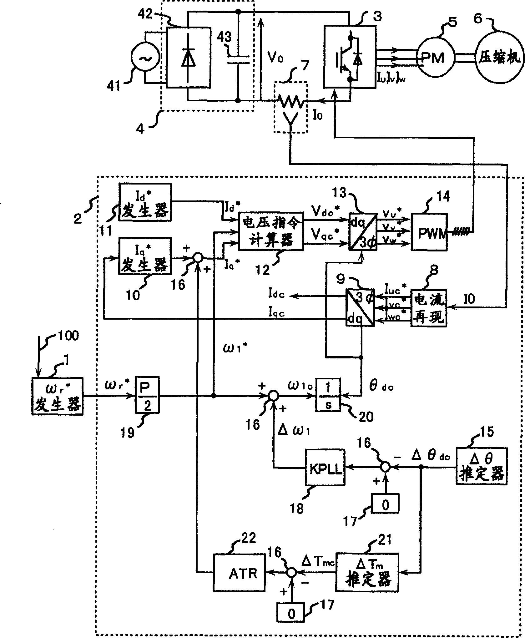
[0032] figure 1 It is a block diagram illustrating the system configuration of Embodiment 1 of the AC motor control device of the present invention. The control device of this embodiment 1 is composed of the following parts: the instruction 100 of the host control device gives the motor a speed command ω r * The speed command generator 1; the controller 2 that calculates the AC applied voltage of the motor and converts it into a pulse width modulation signal (PWM signal) output; the converter (inverter) 3 driven by the PWM signal; the converter 3 that provides power A converter (converter) 4; a PM motor 5 as a control object; a compressor 6 as a load of the PM motor; and a current detector 7 for detecting a current I0 supplied from the converter 4 to the inverter 3 .

[0033] The controller 2 is composed of the following parts: According to the current I0 detected by the current detector 7, the three-phase AC current I flowing on the PM motor 5 is reproduced by calculation i...

Embodiment 2

[0068] Below, use Figure 9 Example 2 of the present invention will be described.

[0069] In Example 1, for the torque ripple vibration frequency ω d , importing a sine wave transfer function with infinite gain. As a result, ω contained in the torque ripple d The components are removed, and the distortion of the driving current of the PM motor increases instead. Since it follows the load torque variation instantaneously, it is unavoidable that the instantaneous current fluctuates greatly. For this reason, the efficiency of the PM motor deteriorates, and abnormalities such as overcurrent trips due to peak currents occur. Therefore, it can be said that the reduction effect of vibration and noise is alleviated as a whole, and on the contrary, it is practical to adjust a compromise point for preventing current distortion.

[0070] Embodiment 2 is to add the function of adjusting the suppression ability to the suppression effect of the periodic disturbance.

[0071] Figure ...

Embodiment 3

[0075] In Embodiments 1 and 2, as a torque controller, the vibration frequency ω of torque ripple d A transfer function with the maximum gain (infinity in Embodiment 1) is introduced. In these controllers, the convergence response of the ripple component is determined by the magnitude of the control gain (control gain 222, or control gain 222B) of the output stage at the final terminal.

[0076] However, the relationship between the set value of these control gains and the actual response time is complicated, and they are studied by making a board diagram, or obtained by simulation tests or actual measurements. Therefore, a lot of effort is required in the adjustment work.

[0077] In Embodiment 3, a torque control device for simplifying adjustment work is provided.

[0078] Figure 10 A configuration example of the torque controller 22C in the third embodiment is shown. by replacing figure 1 Embodiment 3 can be realized by using this torque controller 22C.

[0079] exis...


PUM


Abstract

This invention provides the controller of a synchronous motor. It realizes a low vibration and low noise variable speed drive by suppressing a periodic interference in a driver. When a load unit generates the periodic interference in the driver, it calculates the rotor position of an AC synchronous motor, and by means of detecting a rotating speed directly. The resolving method is that: A sensorless drive is realized by calculating a difference (axial error) between the position of the magnetic flux axis of the AC synchronous motor. The position of the magnetic flux axis assumed in a controller, and correcting the rotating speed, such that the difference becomes zero. Further, according to the calculated value of this axial error, and by means of compensating, it is performed by providing a means for extracting the pulsation component of the torque generated from the motor or the load unit

Description

technical field [0001] The invention relates to a control device, an electrical device and a module of a synchronous motor. Background technique [0002] Various methods have been disclosed so far for the control method of the speed or position sensor not using the AC motor. For example, a method disclosed in JP-A-2001-251889 or the like is known for a permanent-magnet synchronous motor, which is a representative example of an AC motor. This control method does not use a position sensor, but estimates the magnetic pole position inside the controller. [0003] In addition, there are JP-A-10-174488, JP-A-2002-34290, and the like as methods for controlling periodic torque disturbances generated in a load device of an electric motor. In the method described in Japanese Unexamined Patent Publication No. 10-174488, the pulsating portion included in the speed detection value of the motor is extracted, and correction is applied to the inverter output voltage to eliminate the pulsa...

Claims


Application Information

Patent Timeline
IPC IPC(8): F04B49/06H02P6/06H02P6/08H02P6/10H02P6/18H02P6/182H02P6/28H02P21/00H02P21/05H02P21/14H02P21/22H02P23/04H02P23/12H02P23/14H02P27/04H02P27/08
CPCH02P6/10H02P6/18H02P21/0003H02P21/05H02P21/14H02P21/24H02P25/024H02P27/08H02P2207/05
Inventor 岩路善尚远藤常博能登原保夫高仓雄八
Owner HITACHI JOHNSON CONTROLS AIR CONDITIONING INC
Why Eureka
Try Eureka