Pneumatic national flag stand

A national flag and flagpole technology, applied in the field of daily necessities, can solve the problems of limited application scope, high product cost, complex pneumatic devices, etc., and achieve the effects of increasing patriotism, low product cost, and simple and reasonable structure.

Inactive Publication Date: 2005-07-27
侯阜源
View PDF1 Cites 1 Cited by
  • Summary
  • Abstract
  • Description
  • Claims
  • Application Information

AI Technical Summary

Problems solved by technology

However, its pneumatic device is complicated, and it takes up some space when placed, which limits the scope of ap

Method used


Image

  • Pneumatic national flag stand
  • Pneumatic national flag stand
  • Pneumatic national flag stand

Examples


Embodiment Construction

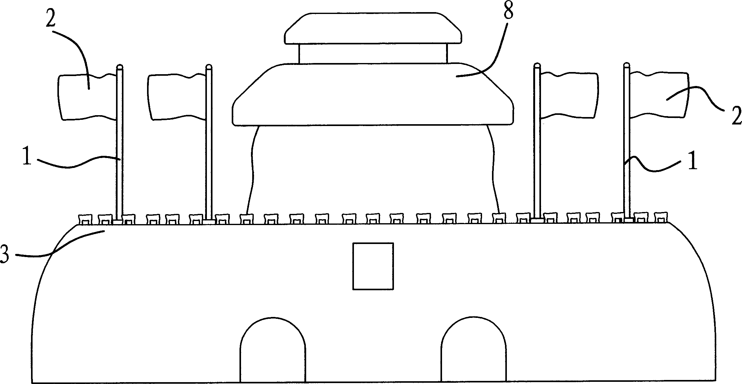
[0017] Such as figure 1 with figure 2 As shown, the pneumatic national flag stand includes a base 3 and a national flag inserted on the base 3 . National flag is made up of flagpole 1 and flag 2, and flag 2 is hung on the top of flagpole 1.

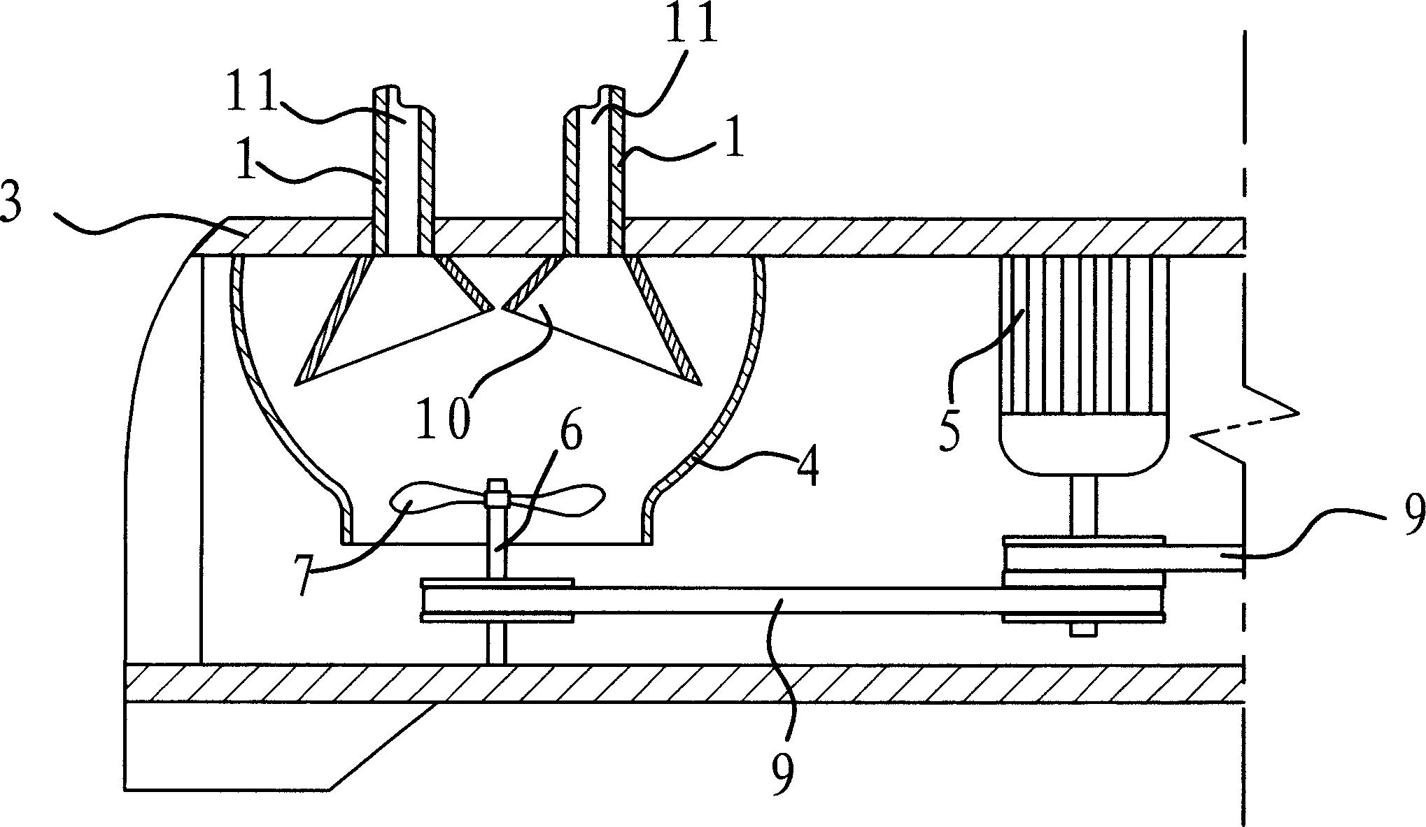
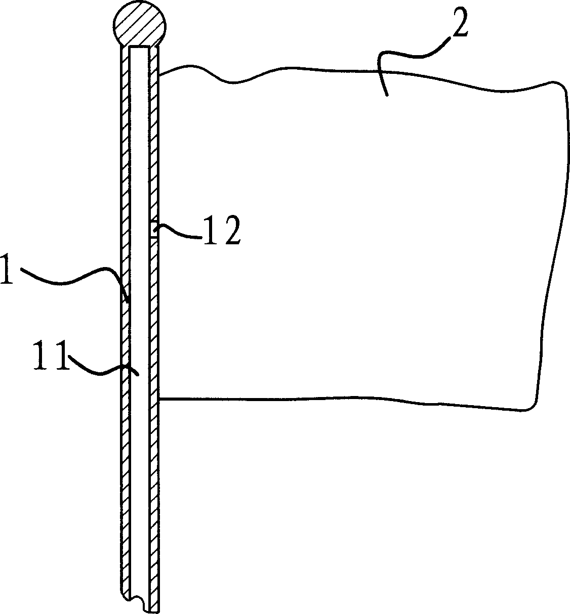
[0018] Such as image 3 As shown, the flagpole 1 is a hollow pipe with an inner chamber 11 at its center. The upper part of the inner cavity 11 is closed, and the lower end communicates with the air duct 4 in the base 3 . There is an air outlet 12 on the top of the flagpole 1, and the air outlet 12 is at the middle of the flag 2.

[0019] Such as figure 2 As shown, there is a fan for generating air flow in the base 3 . In this embodiment, the fan includes a motor 5 , a rotating shaft 6 and an impeller 7 . The impeller 7 is fixed on the rotating shaft 6 . The rotating shaft 6 and the motor 5 are driven by a belt 9 . That is to say, when the motor 5 rotates, the belt 9 drives the rotating shaft 6 and the impeller 7 to rotate toge...


PUM


Abstract

An aerodynamic national flag tower is featured as forming tower with base and national flag on it, forming national flag by flagpole and flag attached on the pole, setting an airguide tube at position corresponding to flagpole, setting up fan in the airguide tube, using hollow pipe as flag pole as its bottom end connected through to airguide tube and top end sealed, having an opening at top portion of flagpole for blowing air out to make flag flutter.

Description

technical field [0001] The invention belongs to the technical field of daily necessities, and relates to a decorative article, in particular to a decorative article which makes the national flag swing through airflow. Background technique [0002] At present, the national flag stand is often placed on the office, desk or negotiation table. In an ordinary national flag stand, the flagpole is inserted into the base, and the flag can only swing with the wind. However, since the national flag stand is mostly placed indoors, there is little wind, so the flag of the national flag has no movement. [0003] For this reason, Chinese patent 98238977.9 provides a kind of "pneumatic national flag seat", which adopts a square base, and the flagpole is provided with an air jet port, and an air pump is placed in the inner groove of the low seat, and the outlet of the air pump is connected with the air inlet at the bottom of the flagpole . The flag base uses an air pump to transport air ...

Claims


Application Information

Patent Timeline
IPC IPC(8): G09F17/00
Inventor 侯阜源
Owner 侯阜源
Why Eureka
Try Eureka