Imaging fault contrast device

A technology of tomography, equipment, applied in the direction of X-ray equipment, computerized tomography scanner, diagnosis, etc.

Inactive Publication Date: 2005-08-03
SIEMENS AG
View PDF11 Cites 4 Cited by
  • Summary
  • Abstract
  • Description
  • Claims
  • Application Information

AI Technical Summary

Problems solved by technology

[0011] Implementation of methods known from the prior art usually requires professionally trained personnel
Furthermore, several known methods are not suitable for balancing the measuring device of the tomography system

Method used


Image

  • Imaging fault contrast device
  • Imaging fault contrast device
  • Imaging fault contrast device

Examples


Embodiment Construction

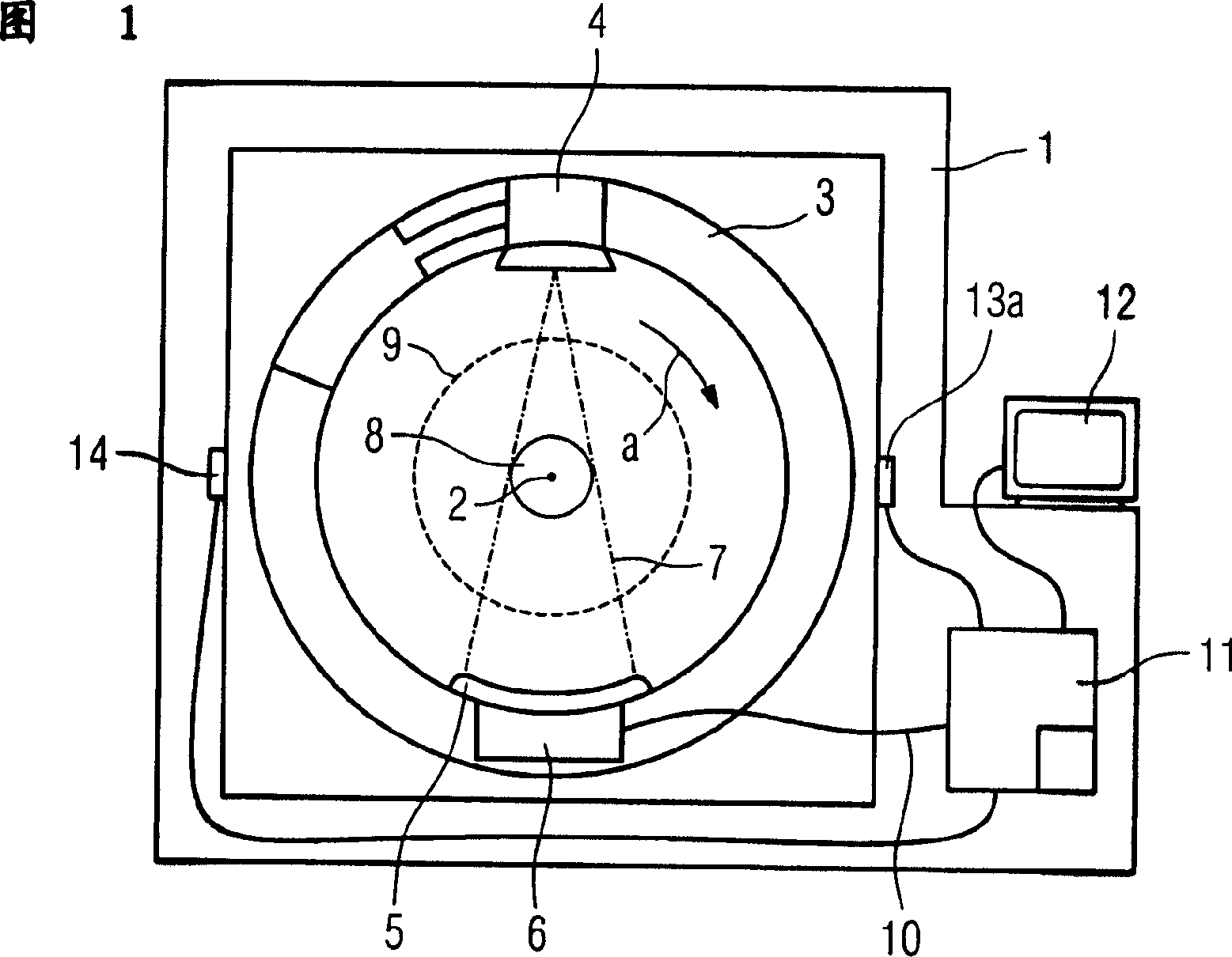
[0023] FIG. 1 schematically shows a side view of a tomography system with a fastening unit 1 . An annular measuring device 3 and a support are arranged on the fixed unit 1 so as to be rotatable around a rotation axis 2 perpendicular to the paper surface. The direction of rotation of the measuring device 3 is marked with an arrow. An x-ray source 4 and an x-ray detector 5 with a downstream evaluation circuit 6 are mounted opposite to the measuring device 3 . The radiation fan 7 emitted by the x-ray source 4 during rotation of the measuring device 3 defines a circular measuring field 8 . The measuring field 8 is located in a patient tunnel 9 shown with dashed lines. In particular, the evaluation circuit 6 is connected via a contact ring connector 10 shown schematically here to a computer 11 which has a monitor 12 for displaying data. Arranged on the fastening unit 1 is a first sensor 13 for measuring vibrations transmitted to the fastening unit 1 . In this case, the sensor i...


PUM


Abstract

The image forming tomography apparatus, particularly an X-ray CT apparatus or an ultrasonic tomography apparatus is so constituted as to be equipped with a fixed side unit (1) having measuring means (13a and 13b) to measure an unbalance, a ring-type measuring apparatus (3) is attached to the fixed side unit (1) to be rotatable around a patient inspection space (9), and balance weights (17a and 17b) to compensate the unbalance are disposed on the measuring apparatus (3), wherein the balance weights (17a and 17b) are attached to an outer peripheral surface (15) of the measuring apparatus (3) with mutually changeable angular position in a rotation path extending in the direction of rotation (a) on two parallel planes (E1 and E2) separated mutually in an axial direction and the two balance weights (17a and 17b) are disposed on each of the planes (E1 and E2).

Description

technical field [0001] The invention relates to an imaging tomography apparatus, in particular an X-ray computed tomography apparatus, which has a stationary unit with measuring elements for measuring unbalances, on which is mounted a ring-shaped measuring device which can be rotated around a patient tunnel A device in which a counterweight for compensating for unbalance is provided on the measuring device. Background technique [0002] Such an X-ray computed tomography system is known from DE-OS 10108065 A1. Wherein, in a fixed space, a measuring device and a bracket that can be rotatably arranged around a horizontal rotation axis are placed. A sensor for detecting the unbalance of the measuring device is arranged on the fixed space. The sensor is connected to a device for calculating the position of the rotatable measuring device at which the counterweight for balancing the imbalance is to be placed. Balancing can be achieved without special balancing equipment. Howeve...

Claims


Application Information

Patent Timeline
Patent Type & Authority Applications(China)
IPC IPC(8): G01M1/16A61B5/05A61B6/00A61B6/03A61B8/00G01M1/02G01M1/32G01M1/36G01M1/38H05G1/04H05G1/60
CPCG01M1/36A61B6/447A61B6/035
Inventor 冈特·丹兹汉斯-于尔根·米勒
Owner SIEMENS AG
Why Eureka
Try Eureka