Antenna for portable radio

A wireless device and portable technology, applied in antennas, resonant antennas, electrical short antennas, etc., can solve problems such as huge radiation directivity, deterioration of transmission and reception performance, etc.

Inactive Publication Date: 2005-08-10
PANASONIC CORP
View PDF3 Cites 12 Cited by
  • Summary
  • Abstract
  • Description
  • Claims
  • Application Information

AI Technical Summary

Problems solved by technology

[0003] However, this prior art built-in antenna has a huge radiation directivity in the direction of the human body
Therefore, there is a problem of deterioration of transmission and reception performance due to the influence of the human body

Method used


Image

  • Antenna for portable radio
  • Antenna for portable radio
  • Antenna for portable radio

Examples


Embodiment 1

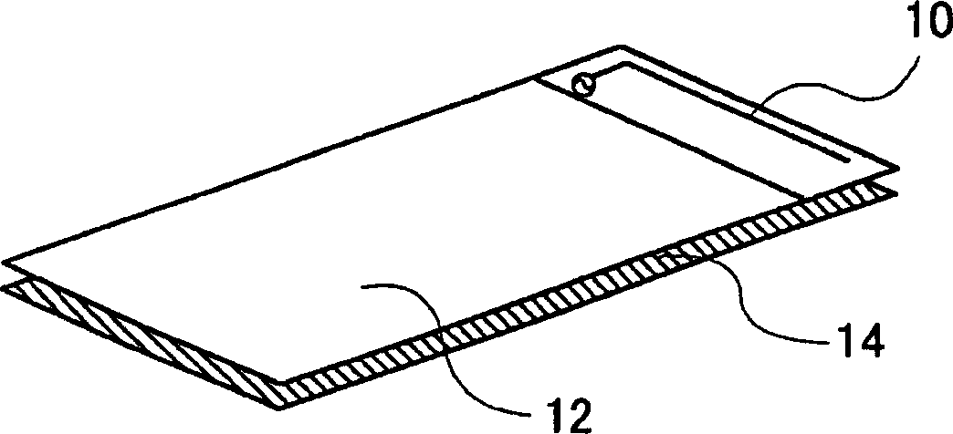
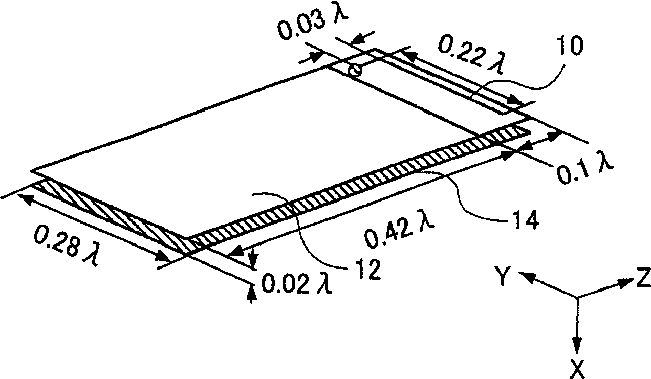
[0032] figure 1 is a schematic diagram of the structure of the portable wireless device antenna according to Embodiment 1 of the present invention. figure 1 The portable wireless device antenna shown in has an inverted L-shaped antenna 10 , a circuit board 12 , and a plate antenna 14 . figure 1 The portable wireless device antenna shown in is built into the portable wireless device.

[0033] The inverted L-shaped antenna 10 is a feeding element, one end of which is electrically connected to a surface of the circuit board 12 through a feeding point. The inverted L-shaped antenna 10 radiates / absorbs radio waves.

[0034] The circuit board 12 is a circuit board of a portable wireless device, to which circuit components including the inverted L-shaped antenna 10 are connected.

[0035] The planar antenna 14 provided at the opposite position on the board face back of the circuit board 12 connected with the inverted L-shaped antenna 10 is a passive element, and the electrical len...

Embodiment 2

[0043] In the portable wireless device antenna according to Embodiment 2 of the present invention: the feeding element is mounted on a circuit board of a predetermined size by meandering it.

[0044] Figure 4 is a schematic diagram of the structure of the portable wireless device antenna according to Embodiment 2. Figure 4 The illustrated portable wireless device antenna includes a meander antenna 20 that replaces figure 1 An inverted L-shaped antenna 10 is shown in the portable wireless device antenna. The rest of the components are with the figure 1 The components of the illustrated portable wireless device antenna are the same, and descriptions are omitted here.

[0045] The meander antenna 20 is a feed element, one end of which is electrically connected to one surface of the circuit board 12 through a feed point, and is an antenna element processed into a meander shape. The meander antenna 20 radiates / absorbs radio waves.

[0046] The plate antenna 14 is connected w...

Embodiment 3

[0051] In the portable wireless device antenna according to Embodiment 3 of the present invention: the inverted L-shaped antenna has a lumped constant element, so that the self-impedance of the inverted L-shaped antenna can be adjusted.

[0052] Figure 5 is a schematic diagram of the structure of the portable wireless device antenna according to Embodiment 3. exist figure 1 A lumped constant element 30 is installed on the inverted L antenna 10 of the shown portable wireless device antenna, namely Figure 5 The structure of the portable wireless device antenna shown in . The rest of the components are with the figure 1 The components of the illustrated portable wireless device antenna are the same, and descriptions are omitted here.

[0053] The lumped constant element 30 is mounted on the inverted L-shaped antenna 10, so that the self-impedance of the inverted L-shaped antenna can be adjusted.

[0054] Here, by adjusting the sizes of the inverted L-shaped antenna 10, the...


PUM


Abstract

The invention relates to an antenna for portable wireless equipments which realizes high-gain and broadband, comprising an inverted L-shaped antenna (10), a circuit board (12) and a plate-shaped antenna (14), wherein, the inverted L-shaped antenna (10) is a feeder element, and one end of the feeder element is electrically connected with one surface of the circuit board (12) via a feed point; the circuit board (12) is in the circuit board of the portable wireless equipment, and the circuit components of the inverted L-shaped antenna (10) are connected with the circuit board; the plate-shaped antenna (14) is opposite to the back surface of the circuit board (12) connected with the inverted L-shaped antenna (10); the plate-shaped antenna is a passive element with the electric length in longitudinal direction being about 1 / 2 of the radio wavelength of the portable wireless equipment; the sizes and the mutual distances of the L-shaped antenna (10), the circuit board (12) and the plate-shaped antenna (14) are regulated to be specific values and both the self-impedance of the inverted L-shaped antenna (10) and the plate-shaped antenna (14) and the mutual impedance of the inverted L-shaped antenna (10) and the plate-shaped antenna (14) are changed together.

Description

technical field [0001] The present invention relates to an antenna for a portable wireless device. Background technique [0002] In recent years, with the rapid spread of communication equipment such as portable wireless equipment, further miniaturization has become an urgent need. With that came the need for a built-in antenna. Currently, Japanese Patent Application Laid-Open No. 2001-244715 discloses a typical use example of such an antenna device. In order to avoid the deterioration of the antenna characteristics due to the influence of the human body, this antenna is designed as a built-in antenna, which can prevent the antenna from causing induced currents on the wireless circuit board by placing the passive components on the feed element . [0003] However, this prior art built-in antenna has a huge radiation directivity in the direction of the human body. Therefore, there is a problem that transmission and reception performance deteriorates due to the influence of...

Claims


Application Information

Patent Timeline
Patent Type & Authority Applications(China)
IPC IPC(8): H01Q1/24H01Q1/38H01Q9/04H01Q9/42H01Q11/04
CPCH01Q9/0442H01Q1/243H01Q9/42H01Q1/38H01Q11/04
Inventor 小岛优
Owner PANASONIC CORP
Why Eureka
Try Eureka