Self-piercing nut

A technology for stamping nuts and nuts, applied in the field of stamping nuts, can solve the problems of smaller pitch of screw holes 23, unable to screw in bolts, insufficient riveting strength, etc., and achieve the effect of large joint area and high riveting strength

Inactive Publication Date: 2005-08-24
SHINJO MFG CO LTD
View PDF1 Cites 4 Cited by
  • Summary
  • Abstract
  • Description
  • Claims
  • Application Information

AI Technical Summary

Problems solved by technology

[0005] As shown in FIG. 9, for the above-mentioned conventional punch nut 21, in the state where it is positioned on the metal panel 35 placed on the riveting die 32, the top surface 22a of the main thread cylinder 22 is pressed by the punch 31. Pressing, under the joint action of the front punching part 25 and the riveting die 32, the peripheral part 36 of the hole punched on the metal panel 35 is riveted by the riveting protrusion 33, and the punching nut 21 is fixed on the metal panel 35, However, when the punch 31 is punching, the main thread cylinder 22 is compressed in the axial direction, so that the pitch of the screw hole 23 may become smaller, resulting in that the bolt cannot be screwed in.
[0006] On the other hand, as shown in FIG. 10, in order to avoid the reduction of the pitch of the screw hole 23, if a cylindrical punch 34 is used to stamp the flange portion 24, since the riveting protrusion 33 of the riveting die 32 is located in the cylindrical The inner side of the punch 34 is not opposite to the punching surface of the punch 34. Therefore, the riveting protrusion 33 cannot achieve a firm riveting effect, and may also cause the problem of insufficient riveting strength.

Method used


Image

  • Self-piercing nut
  • Self-piercing nut
  • Self-piercing nut

Examples


Embodiment Construction

[0038] Hereinafter, specific embodiments of the present invention will be described with reference to the accompanying drawings.

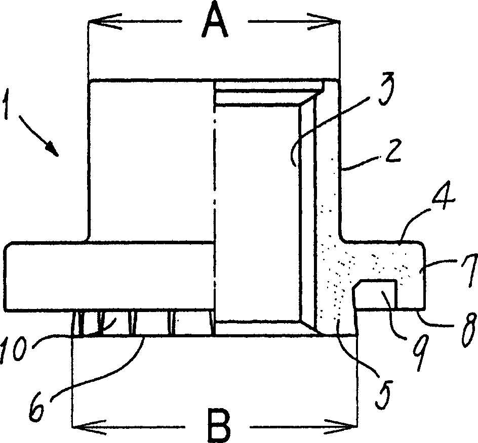
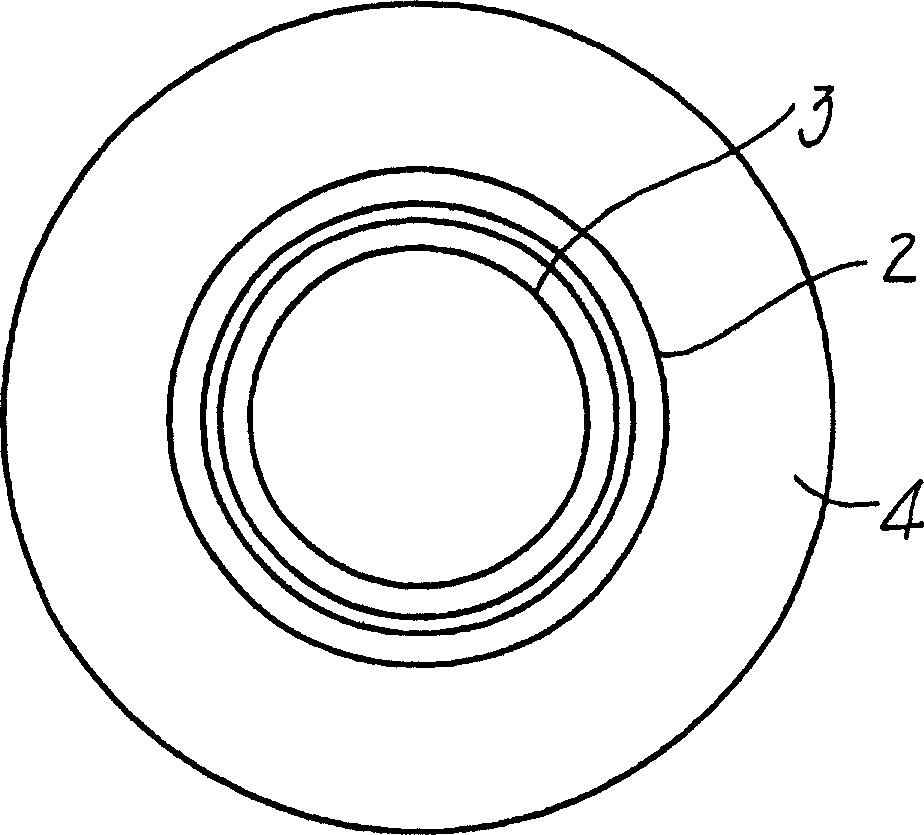
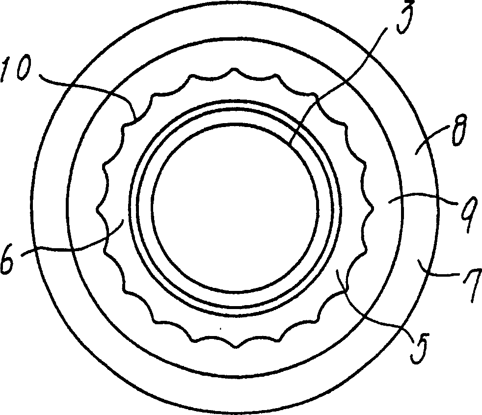
[0039] Figure 1 to Figure 3 An embodiment of the punch nut 1 of the present invention is shown. The punch nut 1 has a large-diameter flange portion 4 at the lower end of a cylindrical main thread cylinder body 2 including a screw hole 3 , and the flange portion 4 is provided with the same main thread cylinder body 2 on the lower center portion of the lower surface. The cylindrical front punch 5 of the shaft, which functions as a punch, that is, punches the metal panel 11 with its end face 6 (see Figure 4 ), an annular outer side wall 7 forming a joint surface 8 is provided on the outer peripheral portion of the lower surface of the flange portion 4, an annular groove 9 is formed between the front punch portion 5 and the annular outer wall 7, and the front punch portion The end face 6 of 5 protrudes from the joint face 8 . The screw hole 3 exte...


PUM


Abstract

A self-piercing nut has a main threaded cylinder ( 2 ) and a pilot ( 5 ) surrounding a threaded bore ( 3 ). The main cylinder has a lower end continuing to a flange ( 4 ), with the pilot ( 5 ) protruding from a central bottom of the flange so as to pierce a hole in a metal panel ( 11 ). A skirt ( 7 ) depends from the flange's periphery to serves as a seat ( 8 ) contacting the panel. An annular groove ( 9 ) is defined between the pilot ( 5 ) and skirt ( 7 ) such that the pilot is projected beyond the seat ( 8 ). The end face ( 6 ) of pilot has an outer diameter 'B' larger than that 'A' of the lower end of main cylinder ( 2 ). The outer periphery of pilot ( 5 ) is tapered to decrease its diameter inwards and to-wards the nut axis, and a corrugation ( 10 ) is formed in the outer periphery or in the inner periphery of skirt ( 7 ).

Description

technical field [0001] The invention relates to a punching nut, the main body of which has the function of punching a metal panel, and is riveted with the peripheral edge of a hole punched in the metal panel, and then fixed on the above-mentioned metal panel, in particular to a nut that can be firmly The punched nut that is fixed on the metal panel of soft material such as aluminum plate. Background technique [0002] In recent years, for the punched nut used in the body panel of an automobile, the joint area needs to be increased for the sake of strength. In particular, soft and easily deformable metal panels such as aluminum sheets used to reduce the weight of automobiles require a larger bonding area. [0003] In order to meet such a need, for example, Patent Document 1 discloses a punched nut with an increased engagement area. [0004] As shown in FIGS. 9 and 10 , the nut main body including the screw holes 23 has a large-diameter flange portion 24 at the lower end of ...

Claims


Application Information

Patent Timeline
Patent Type & Authority Applications(China)
IPC IPC(8): F16B37/04F16B37/06
CPCF16B37/068
Inventor 新城忠
Owner SHINJO MFG CO LTD
Why Eureka
Try Eureka