

Light-emitting apparatus and illuminating apparatus
A technology for light-emitting devices and light-emitting elements, which is applied to lighting devices, lighting and heating equipment, light sources, etc., can solve problems such as difficulty in controlling color temperature, improve the intensity of radiated light, suppress the deviation of color spots and illuminance distribution, and suppress the Light Efficiency Reduction Effect
- Summary
- Abstract
- Description
- Claims
- Application Information
AI Technical Summary
Problems solved by technology
Method used
Image

Examples
Embodiment 1
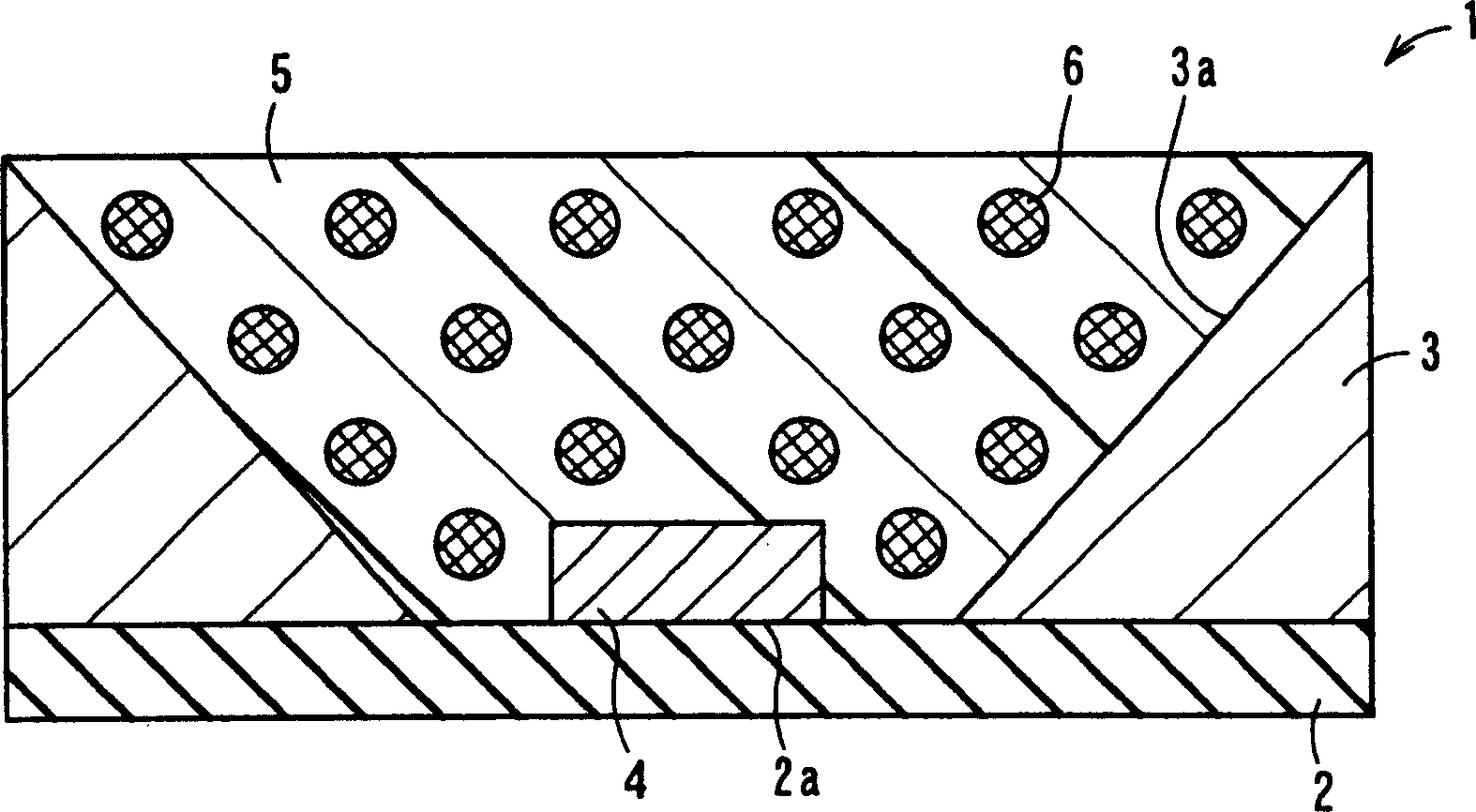
[0100] First, an alumina ceramic substrate is prepared as a material of the base body 2 .
[0101] The substrate 2 is a rectangular flat plate with a length of 3.5 mm x a width of 3.5 mm x a thickness of 0.5 mm, and has a mounting portion 2a on which a light-emitting element 4 is mounted in the center of the upper surface, and a wiring conductor made of W metal facing downward from the mounting portion 2a.
[0102] In addition, the housing 3 is prepared. The frame body 3 is formed in a cylindrical shape with a diameter of 3.5 mm, a height of 1.5 mm, an upper opening of 3.3 mm in diameter, and a lower opening of 0.5 mm in diameter.
[0103] Next, the electrodes will be provided with Au-Sn The light-emitting element 4 that emits near-ultraviolet light with a thickness of 0.08 mm of the pad, through which Au-Sn The pad is bonded to the wiring conductor, and the reflective member 2 is bonded to the outer peripheral portion of the upper surface of the base body 1 with a resin adh...
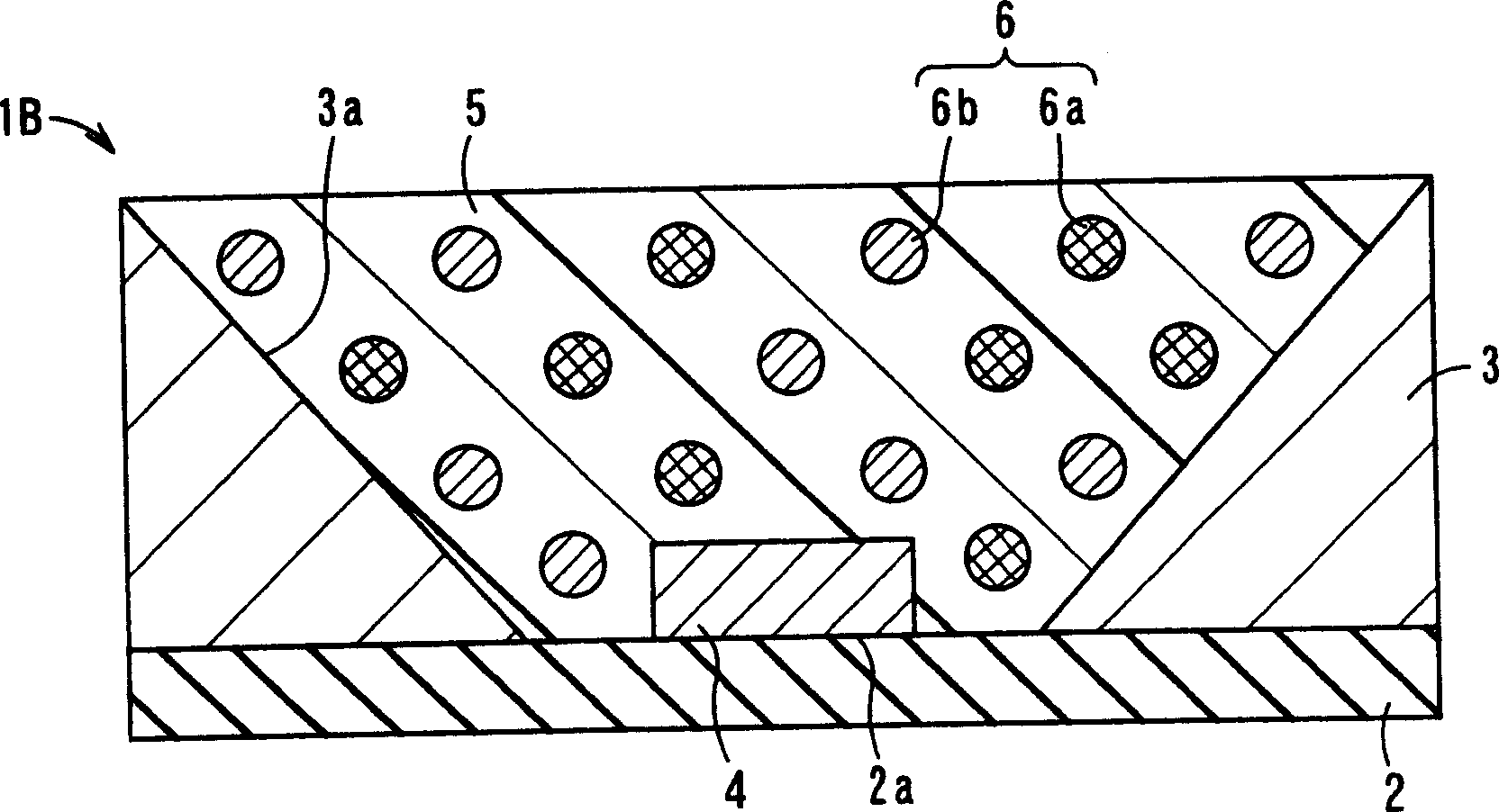
Embodiment 2
[0110] Below, refer to image 3 An example of the light-emitting device 1B of the present invention will be described.
[0111] In Example 2, in the light-emitting device 1B, the configurations of the base body 2 and the frame body 3 are the same as those of the first embodiment.
[0112] In addition, regarding the density of the phosphor 6, as in Example 1, the red phosphor (La 2 o 2 S:Eu) is 5.8g / cm 3 , green phosphor (BaMgAl 10 o 17 :Eu) is 3.8g / cm 3 , blue phosphor (BaMgAl 10 o 17 :Eu, Mn) is 3.8g / cm 3 . These three types of phosphors 6 are respectively blended so that the color temperature of light emitted from the light emitting device 1 becomes 6500K.
[0113] The light-transmitting member 5 is made of silicone resin with a viscosity of 0.3, 0.4, 1.3, 10, 50, and 55 Pa·s before curing, and three kinds of phosphors 6 that emit red light, green light, and blue light are added to the light-transmitting member 5. After the silicone resin was stirred to make the f...
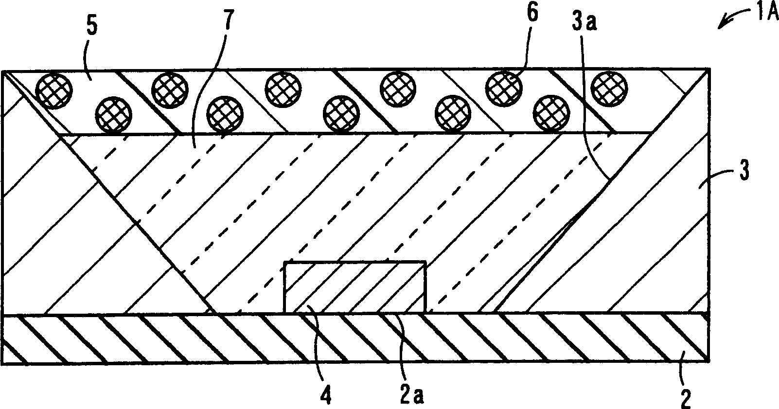
Embodiment 3
[0120] In Example 3, in the light-emitting device, the configurations of the base body 2 and the frame body 3 are the same as those in Example 1. FIG.
[0121] Regarding the density of phosphor 6, the red phosphor (La 2 o 2 :Eu) is 5.8g / cm 3 , green phosphor ((BaMgAl) 10 o 12 :Eu, Mn) is 3.8g / cm 3 , blue phosphor ((Sr, Ca, Ba, Mg) 10 (PO 4 ) 6 o 12 :Eu) is 3.8g / cm 3 . Mix these 3 phosphors 6 .
[0122] The light-transmitting member 5 used a silicone resin whose viscosity before curing was 1.7 Pa·s, and vacuum degassed it with a vacuum defoamer in an uncured state. In the vacuum degassed silicone resin, the volume of the phosphor reaches 1 / 30 times, 1 / 24 times, 1 / 18 times, 1 / 15 times, 1 / 12 times, 1 / 6 times the volume of the silicone resin 1 / 5 times, 1 / 5 times, respectively mixed phosphor 6 mixed in such a way that the required visible light can be output inside. That is, in the vacuum defoamed silicone resin, according to the volume ratio of phosphor and silicone r...
PUM
 Abstract
Description
Claims
Application Information