Dust collector expansion pipe

A telescopic tube, vacuum cleaner technology, applied in the direction of vacuum cleaners, suction hoses, cleaning equipment, etc., can solve the problems of easy disengagement of positioning rollers, large radial size of locking parts, and unreliable locking, and achieves compact structure and convenient adjustment. , lock reliable effect

Inactive Publication Date: 2005-10-26
沈盘根
View PDF1 Cites 7 Cited by
  • Summary
  • Abstract
  • Description
  • Claims
  • Application Information

AI Technical Summary

Problems solved by technology

However, the locking mechanism of this dust suction pipe is basically the same as the above-mentioned prior art, and still relies on the upper and lower limits of the positioning rollers to fall into the U-shaped groove to achieve the purpose of locking. Therefore, when the inclined surface of the push plate is worn or deformed, the positioning rollers The column is easy to fall out, the locking is not reliable enough, and the radial dimension of the locking part is large

Method used


Image

  • Dust collector expansion pipe
  • Dust collector expansion pipe
  • Dust collector expansion pipe

Examples


Embodiment 1

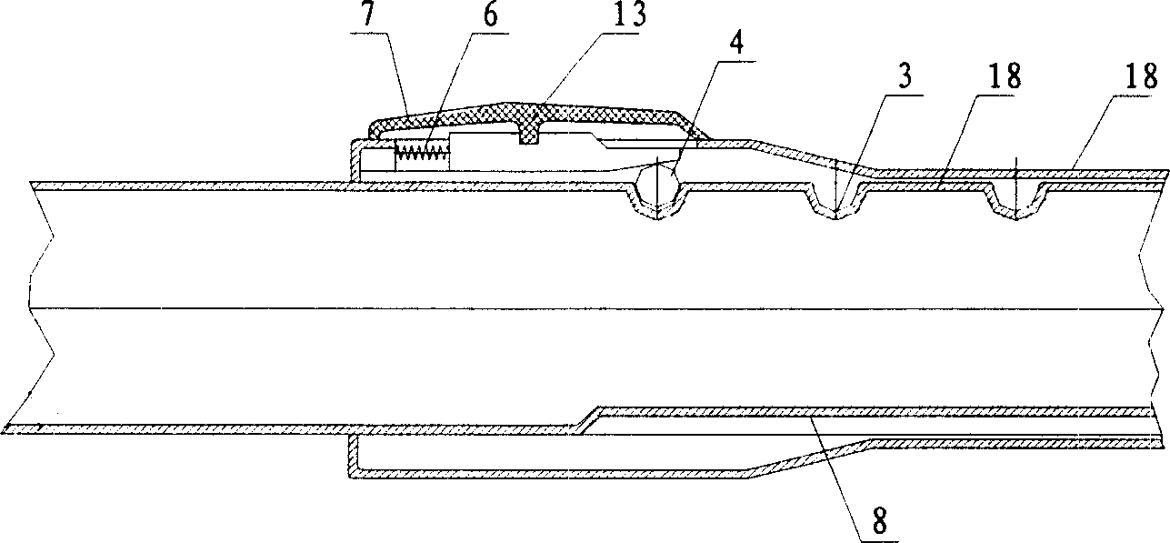
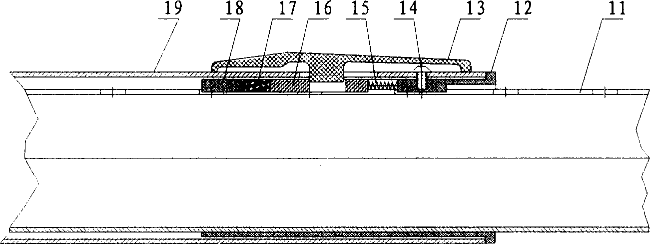
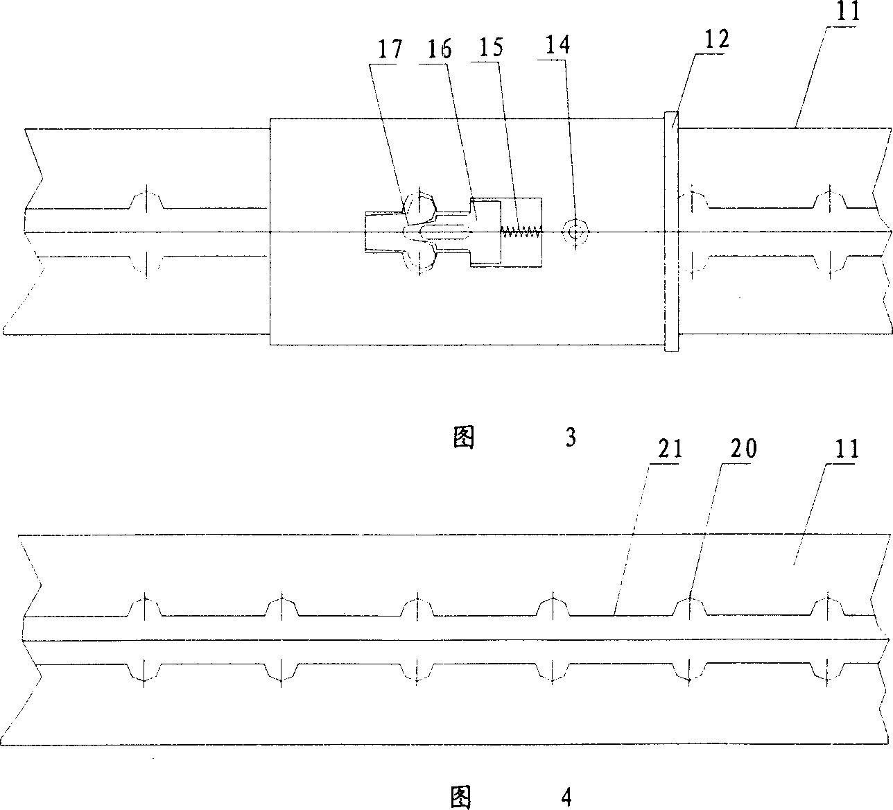
[0014] The telescoping tube of the vacuum cleaner of the present embodiment is as figure 2 , 3, and 4, it mainly consists of the inner tube 11 and outer tube 18 that are nested with each other, the joint sleeve 12 that is fixedly connected to the end of the outer tube by means of screws 14, the elastic V-shaped locking piece 17 and the locking mechanism composed of the latch block 16. . The outer wall of the inner tube 11 is provided with an axial chute 21 as shown in FIG. 4 , and two sides of the axial chute are formed with substantially symmetrical circumferential U-shaped grooves 20 at intervals. The joint cover 12 is shaped on the perforation similar to the envelope shape of the elastic V-shaped locking piece 17 and the latch block 16 . The elastic V-shaped locking plate 17 of the locking mechanism is formed with a symmetrical arc lug matching the U-shaped groove 20, and one end passing through the hole on the joint sleeve 12 falls into the axial slide groove 21, and the...


PUM


Abstract

A telescopic tube with the improved locking mechanism for cleaner is composed of mutually sleeved internal and external tubes. Said internal tube has the axial slide slot with symmetrica U-shaped notches at intervals. Said external tube has one end fixed to a join sleeve which has a locking unit consisting of a V-shaped elastic locking sheet arranged in said slide slot of internal tube and a pin block inserted in said V-shaped opening and pressed by a spring.

Description

technical field [0001] The invention relates to a part of a vacuum cleaner, in particular to a structural improvement of a locking mechanism for a telescoping tube of a vacuum cleaner, which belongs to the technical field of household appliances. Background technique [0002] In order to meet the requirement of existing vacuum cleaners for adjusting the length of the suction pipe, the suction pipe is often designed as a telescopic locking structure. Its typical structure is as figure 1 Shown, mainly by outer tube 18, inner tube 11, positioning roller 4, pressing push button 13 to form. The inner tube 11 is provided with some positioning recesses 3, and an inclined-plane push plate is installed under the pressing push button 5, and the pressing push button can make the positioning roller 4 fall into the positioning recess 3, thereby locking the inner and outer pipes of the adjusted length. However, the axial chute 6 and the radial positioning recess 3 of this locking struct...

Claims


Application Information

Patent Timeline
Patent Type & Authority Applications(China)
IPC IPC(8): A47L9/00A47L9/24
CPCA47L9/244
Inventor 沈盘根
Owner 沈盘根
Why Eureka
Try Eureka