A device and a method for driving an elevator door

A door drive and power supply technology, applied in the field of elevator door devices, can solve the problems of increased number of control elements, increased cost, increased energy consumption, etc.

Inactive Publication Date: 2005-11-23
EMT INT CO LTD
View PDF0 Cites 8 Cited by
  • Summary
  • Abstract
  • Description
  • Claims
  • Application Information

AI Technical Summary

Problems solved by technology

[0011] According to the conventional door driving device 100 used in the conventional elevator door system 1, since the driving operation of the motor 14 is entirely dependent on the switching states of the limit switches 20a and 20b, there is a problem that it is difficult to perform smooth driving to open or close the door.
[0012] In addition, in the case of installing additional components to compensate for control accuracy, problems such as increased cost, increased energy consumption, increased number of control elements, increased difficulty in control stability, etc. are caused

Method used


Image

  • A device and a method for driving an elevator door
  • A device and a method for driving an elevator door
  • A device and a method for driving an elevator door

Examples


Embodiment Construction

[0027] Hereinafter, preferred embodiments of the present invention will be described in detail with reference to the accompanying drawings.

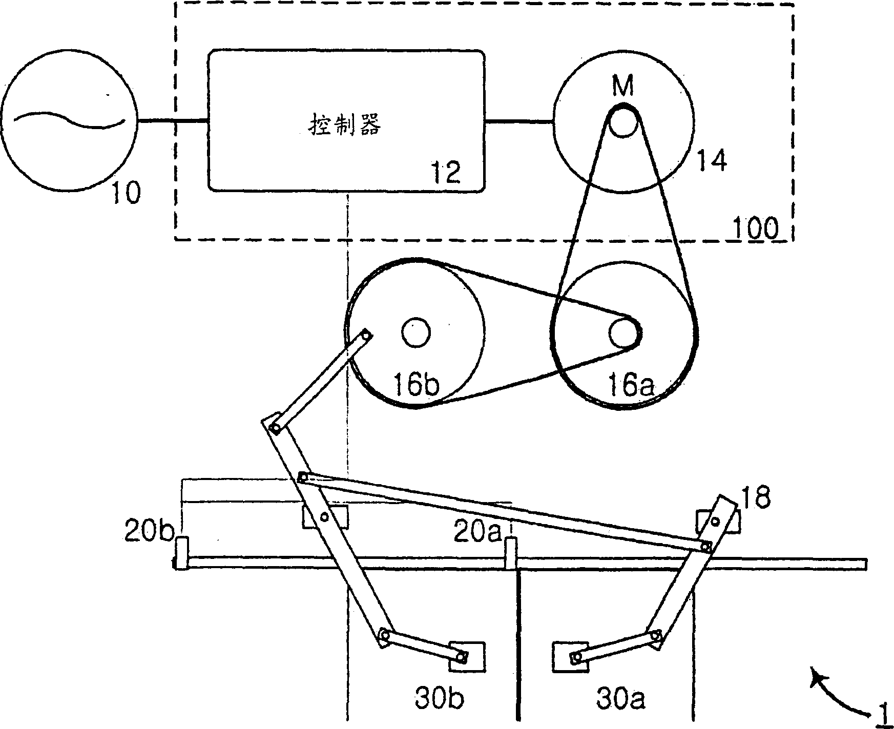
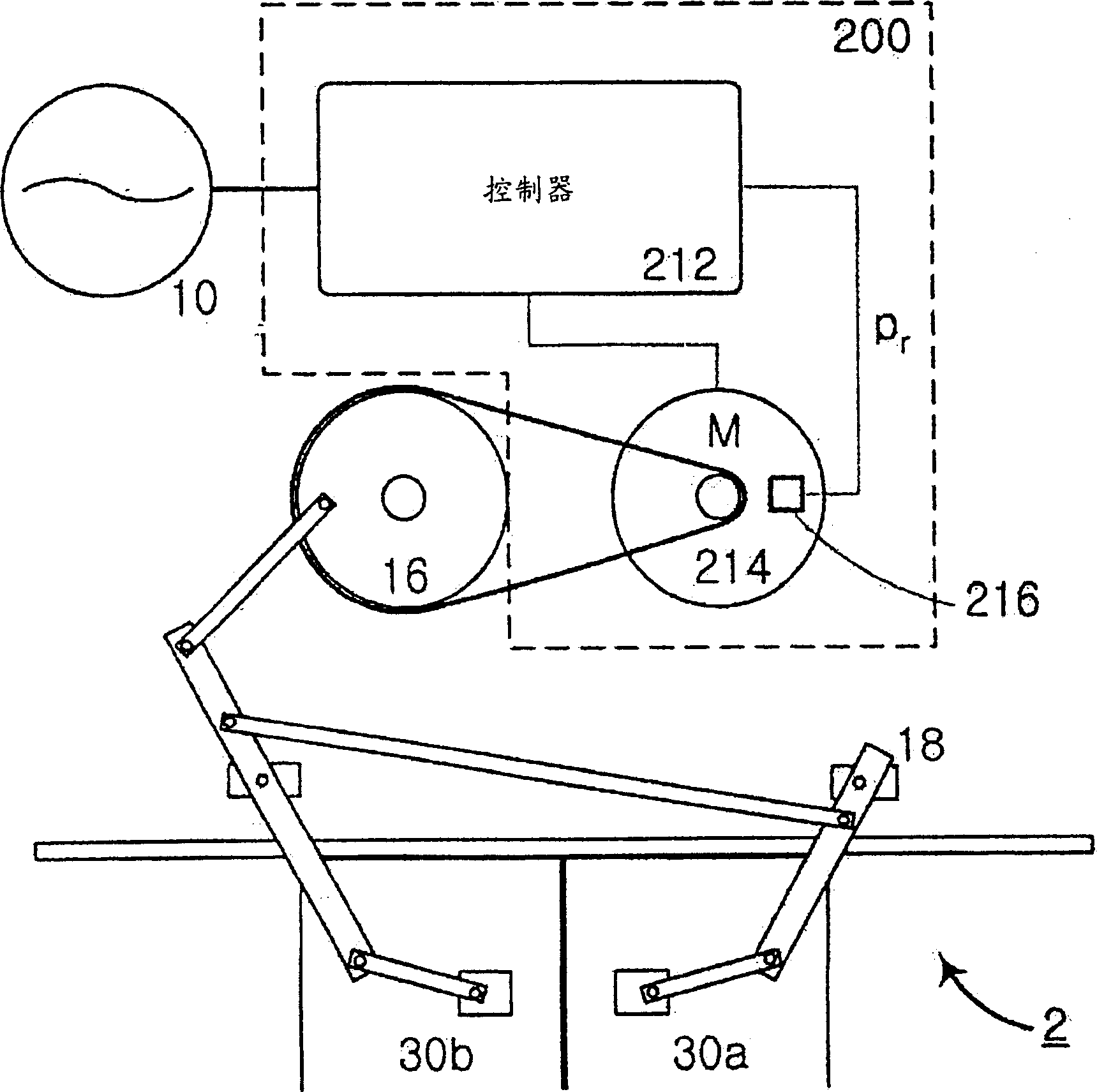
[0028] refer to figure 2 , figure 2 An embodiment of an elevator door drive according to the invention and a block diagram of an elevator door system including the elevator door drive are shown. Such as figure 2 As shown, the elevator door system 2 including the door driving device 200 of the present invention includes: a power supply 10 for providing electric power; a pair of doors 30a and 30b are opened or closed by moving back and forth in a predetermined moving distance; the door driving device 200, for driving the doors 30a and 30b by using power supplied from the power source 10; and a power transmission unit, ie, a pulley 16 and a robot arm 18 for transmitting torque from the door driving device 200 to the doors 30a and 30b.

[0029] Details, modifications, and applications of power supply 10, doors 30a and 30b, and power tr...


PUM


Abstract

A device and a method for driving an elevator door which uses a brushless DC motor for providing sliding force.

Description

technical field [0001] The present invention relates to an apparatus and method for driving elevator doors. More particularly, the present invention relates to an apparatus and method for driving an elevator door mounted on an elevator to automatically open and close. Background technique [0002] Typically, an elevator includes an elevator car and a pair of doors at each floor landing. A door driving device for driving these doors is installed at a predetermined position of the elevator car. When the elevator car arrives at the landing of each floor, a pair of doors of the elevator car and the pair of doors of the landing are engaged with each other and are opened or closed by a door driving device installed in the elevator car. An elevator door system is defined as a device comprising the door drive described hereinafter and other mechanical or electrical elements for opening or closing the doors. [0003] refer to figure 1 , describes an example of a well known door d...

Claims


Application Information

Patent Timeline
IPC IPC(8): B66B13/00B66B13/14
CPCB66B13/146B66B13/00
Inventor 沈东埈尹智泽
Owner EMT INT CO LTD
Why Eureka
Try Eureka