
Device for detecting absolute rotation angle and torque

A technology of absolute rotation and detection device, which is applied in the direction of measuring device, torque measurement, transportation and packaging, etc., and can solve the problems of larger detection device, non-detection of absolute angle, and larger size of detection device

Inactive Publication Date: 2005-11-23
PANASONIC CORP
View PDF0 Cites 15 Cited by
  • Summary
  • Abstract
  • Description
  • Claims
  • Application Information

AI Technical Summary

Problems solved by technology

[0003] However, in order to obtain a high-precision rotation angle, the code plate needs a plurality of magnetic poles, so there is a problem that the detection device becomes larger
In addition, disposing the magnetic detection element 22 in the radial direction of the code plate 20 also increases the size of the detection device.
[0004] Also, this existing device does not detect the absolute angle

Method used


Image

  • Device for detecting absolute rotation angle and torque
  • Device for detecting absolute rotation angle and torque
  • Device for detecting absolute rotation angle and torque

Examples


Embodiment Construction

[0013] Embodiments of the present invention will be described below with reference to the drawings.

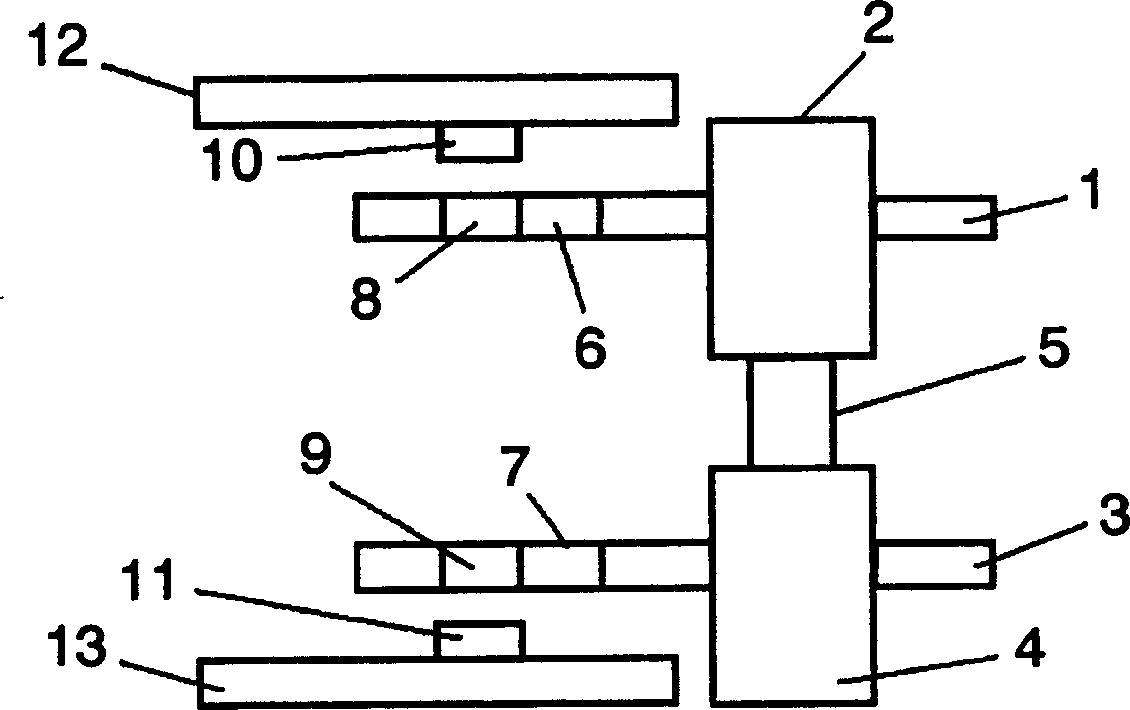
[0014] figure 1 The structure of the absolute rotation angle and torque detection device of this embodiment is shown. The torsion bar unit is composed of an input shaft 2 , a torsion bar 5 , and an output shaft 4 arranged concentrically on the same rigid body. The first gear 1 and the second gear 3 are connected to the input shaft 2 and the output shaft 4 of the torsion bar unit, respectively. The first gear 1 cooperates with gear A6, and the second gear cooperates with B7. The first magnet 8 is provided at the center of the gear A6, and the second magnet 9 is provided at the center of the gear B7. The first magnet 8 and the second magnet 9 are magnetized by one pole pair. The first magnetic detection element 10 mounted on the substrate 12 is arranged at a position facing the first magnet 8 , and the second magnetic detection element 11 mounted on the substrate 13 is arra...


PUM


Abstract

A detector of an absolute rotation angle and torque is disclosed. The detector includes a first gear (1) coupled to an input shaft (2) of a torsion-bar unit, a gear A (6) engaging with the first gear (1), and a first detecting section of an absolute rotation angle placed at the center of the gear A (6). The detector also includes a second gear (3) coupled to an output shaft (4) of the torsion-bar unit, a gear B (7) engaging with the second gear (3), and a second detecting section of an absolute angle placed at the center of gear B (7).

Description

technical field [0001] The present invention relates to a device mounted on a torsion bar that simultaneously detects absolute rotational angle and torque. The detecting device of the present invention is used in a power steering device of an automobile and the like. Background technique [0002] Image 6 It is an existing detection device for rotation angle and torque. The gear 18 is mounted on an input shaft (not shown) of the torsion bar. A gear 21 cooperating with the gear 18 has a circular symbol plate 20 with a plurality of magnetic poles. The symbol plate 20 rotates with the rotation of the input shaft. The magnetic detection element 22 detects the rotation angle of the input shaft by counting the number of rotating magnetic poles. The gear 42 is mounted on the output shaft (not shown) of the torsion bar, and the rotation angle of the output shaft is detected in the same manner as above. When the torsion bar is activated to twist the shaft, the torque is detected...

Claims


Application Information

Patent Timeline
Patent Type & Authority Applications(China)
IPC IPC(8): B62D5/04B62D5/06B62D6/10B62D15/02G01B7/00G01B7/30G01D5/14G01D5/16G01D5/245G01L3/10
CPCG01L3/101G01L3/104B62D15/0215B62D6/10B62D15/0245G01D5/145G01D2205/28G01D2205/26
Inventor 御池幸司植平清孝牛原正晴
Owner PANASONIC CORP
Learn More