Geared motor

a geared motor and motor shaft technology, applied in the direction of electronic commutators, program control, instruments, etc., can solve the problem of requiring a considerable amount of time for origin return movements, and achieve the effect of good precision, fast calculation, and omission of wasteful rotational movements

Active Publication Date: 2008-05-20
HARMONIC DRIVE SYST IND CO LTD
View PDF4 Cites 17 Cited by
  • Summary
  • Abstract
  • Description
  • Claims
  • Application Information

AI Technical Summary

Benefits of technology

[0010]An main object of the present invention is to provide a geared motor that can rapidly carry out movements for ascertaining the mechanical starting point with good accuracy.
[0011]In order to solve the above and other problems, the present invention provides a geared motor in which a reduction gear is connected to a motor shaft, having a motor encoder for outputting A-, B-, and Z-phase signals in accompaniment with the rotation of the motor shaft; an output-side absolute value encoder for detecting the absolute rotational position of an output shaft of the reduction gear; and a drive control circuit for obtaining the mechanical starting point of the motor shaft and the output shaft on the basis of the detection value of the motor encoder and the absolute value encoder, wherein the absolute value encoder has a precision that allows the rotational angle of the output shaft per single rotation of the motor shaft to be detected.

Problems solved by technology

Nevertheless, there is a problem in a conventional geared motor in that a considerable amount of time is required in the origin return movements.

Method used


Image

  • Geared motor
  • Geared motor
  • Geared motor

Examples


embodiment 1

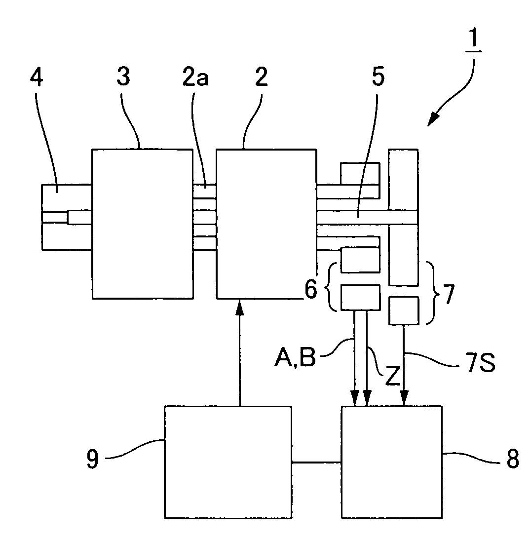
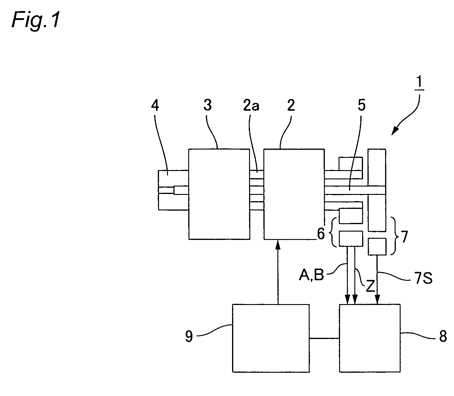
[0045]FIG. 1 is a schematic structural diagram showing a geared motor in which the present invention has been applied. The geared motor 1 has a motor main body 2, a wave reduction gear 3 coaxially connected to a motor shaft 2a extending from the front end of the motor main body 2, and an output shaft 4 coaxially connected to the front end of the wave reduction gear 3.

[0046]The wave reduction gear 3 is a cup-shaped wave reduction gear, for example, and has an annular rigid internally toothed gear, a cup-shaped flexible externally toothed gear disposed inside thereof, and an elliptically contoured wave generator (not shown) fitted therein. When the wave generator rotates, the meshing position of the flexible externally toothed gear with the annular rigid internally toothed gear moves circumferentially, and a relative rotation is generated in accordance with the difference in the number of internal and external teeth. The rigid internally toothed gear is ordinarily the fixed side, the ...

embodiment 2

[0061]Next, FIG. 5 is a schematic structural diagram showing another example of a geared motor in which the present invention has been applied. Since the basic configuration of the geared motor 1A shown in the diagram is the same as that of FIG. 1, the same reference numerals are assigned to the corresponding locations and a description thereof is omitted.

[0062]In the geared motor 1A of the present example, the difference is that an input-side absolute value encoder 10 is mounted on the motor shaft 2a. When absolute value encoders 7 and 10 are disposed on both of the shafts 2a and 4, and when the power is switched on, the mechanical starting point is immediately calculated from the absolute rotational angle positions (signals 10S and 7S) of the shafts 2a and 4 obtained from the two absolute value encoders 7 and 10. Thus, rotation movements for ascertaining the mechanical starting point are not required at startup and at other times.

[0063]In the present example as well, when the numb...


PUM


Abstract

A motor encoder is mounted on a motor shaft of a geared motor 1, and the origin position is detected by using a Z-phase signal. An absolute value encoder with a precision that allows the number of motor rotations to be determined is mounted on an output shaft 4 of a reduction gear, and the absolute rotational position thereof is detected. When the first Z-phase signal generated in conjunction with the rotation of the motor shaft 2a is obtained at startup and at other times, the mechanical starting point at which the motor shaft and output shaft are both positioned at the origin can be calculated based on the absolute rotational position of the reduction-gear output shaft obtained from the output-side absolute value encoder. Since the mechanical starting point is obtained by rotating the motor shaft a single rotation at most, the time required to calculate the mechanical starting point is short in comparison with conventional examples, and extraneous rotational movements can be avoided.

Description

BACKGROUND OF THE INVENTION[0001]1. Field of the Invention[0002]The present invention relates to a geared motor, and more particularly to a geared motor that can rapidly and precisely detect the mechanical starting point of an output shaft of a reduction gear during motor startup and at other times.[0003]2. Description of the Related Art[0004]Geared motors are used that are configured to output the rotational output of a motor in the drive section of industrial robots, machine tools, and the like via a reduction gear having high transmission accuracy. Such drive sections require high positioning accuracy. As shown in FIG. 11, a geared motor 101 has a motor main body 102, a reduction gear 103 coaxially connected to a motor shaft 102a of the motor main body 102, and an output shaft 104 coaxially connected to the output side of the reduction gear 103. A wave gear drive, for example, is used as the reduction gear 103.[0005]In a geared motor 101, the rotational angle of the output shaft ...

Claims


Application Information

Patent Timeline
Patent Type & Authority Patents(United States)
IPC IPC(8): G05B19/29
CPCH02P6/165H02P6/17
Inventor MIYASHITA, KUNIOKOYAMA, JUNJIMITAMURA, MUNEOSAWAMURA, YASUO
Owner HARMONIC DRIVE SYST IND CO LTD
Why Eureka
Try Eureka