Magnetic encoder and method of detecting absolute rotational position

a technology of absolute rotation and magnetic encoder, which is applied in the field of magnetic encoder, can solve the problems of increasing precision, time is required to make such adjustments, and problems such as problems presented, and achieve the effect of high resolution, without increasing resolution and precision

Active Publication Date: 2011-02-03
HARMONIC DRIVE SYST IND CO LTD
View PDF4 Cites 17 Cited by
  • Summary
  • Abstract
  • Description
  • Claims
  • Application Information

AI Technical Summary

Benefits of technology

[0056]According to the method of detecting absolute rotational position of the present invention, the resolution for detecting the absolute position of the rotating shaft is prescribed by Pp×Rm, where Rm is the resolution of the multi-pole absolute-value encoder. Detection precision is dependent solely on the resolution of the multi-pole absolute-value encoder. The resolution and prec...

Problems solved by technology

The precision of the two-pole magnetic encoder must therefore be further increased in order to obtain output having higher precision, and increasing precision is therefore difficult.
The start point...

Method used


Image

  • Magnetic encoder and method of detecting absolute rotational position
  • Magnetic encoder and method of detecting absolute rotational position
  • Magnetic encoder and method of detecting absolute rotational position

Examples


embodiment 1

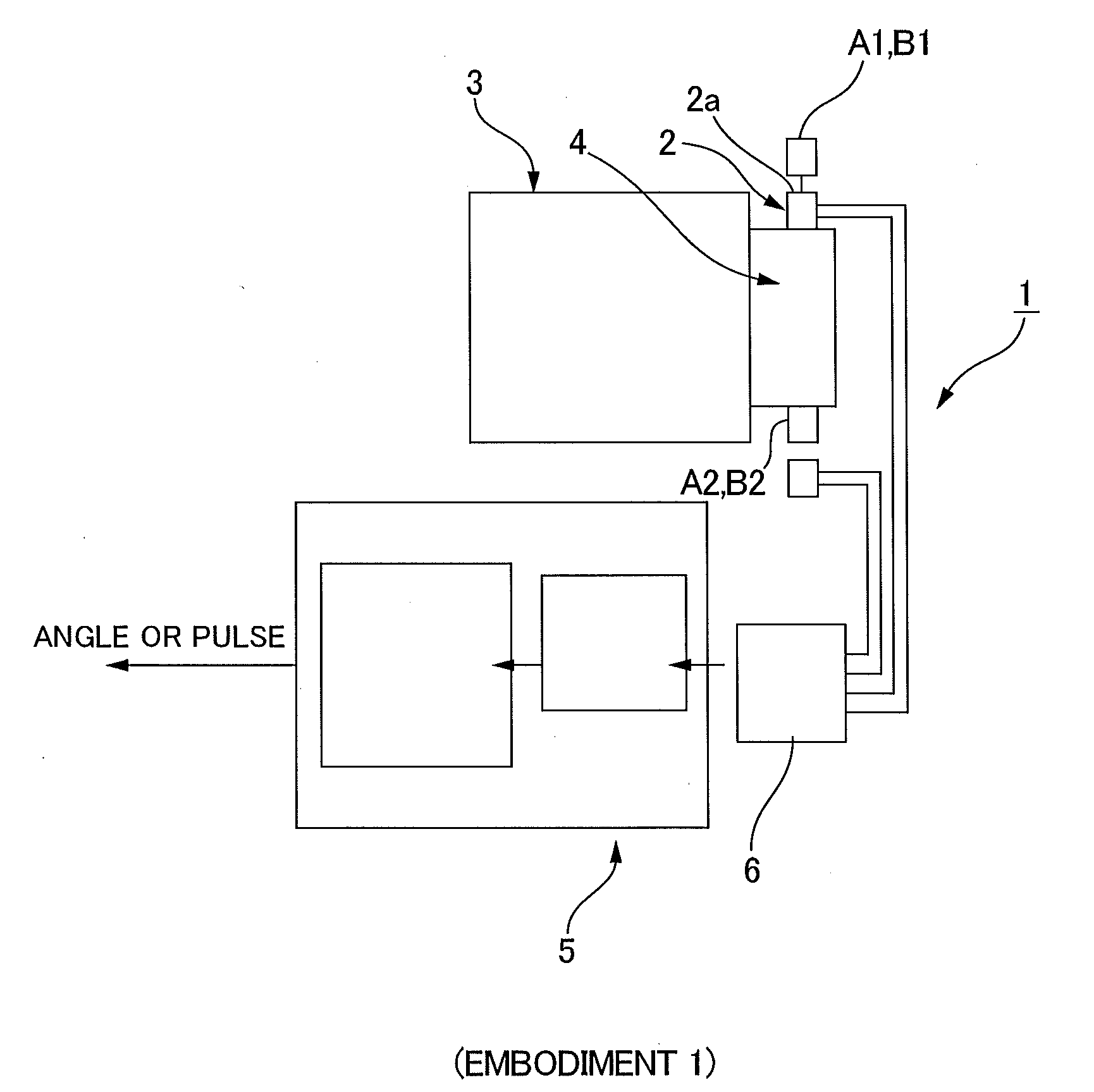
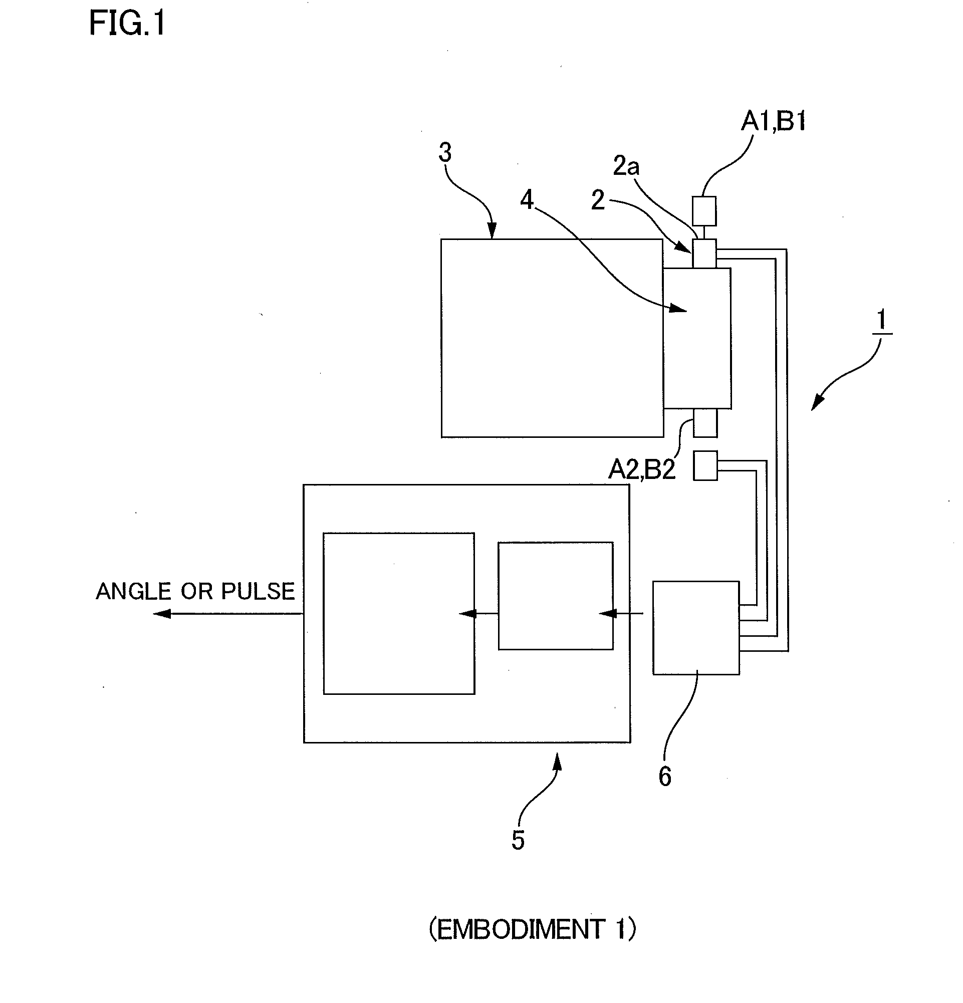
[0076]FIG. 1 is a schematic block diagram showing a magnetic encoder provided with a multi-pole magnet in which the present invention has been applied. The magnetic encoder 1 has a multi-pole magnet 2 in which N-poles and S-poles are formed in alternating fashion at equiangular intervals along the circumferential direction, first and second magnetic detecting elements A1, B1 adjacently arranged along the circular external peripheral surface 2a of the multi-pole magnet 2, third and fourth magnetic detecting elements A2, B2 adjacently arranged along the circular external peripheral surface 2a of the multi-pole magnet, and a signal processing circuit 5 for generating signals that represent the rotational position of a rotating shaft of a structure in which detection is to be carried out, e.g., a rotating shaft 4 of a servo motor 3, wherein the signals are generated on the basis of the first to fourth magnetic detecting elements A1 to B2.

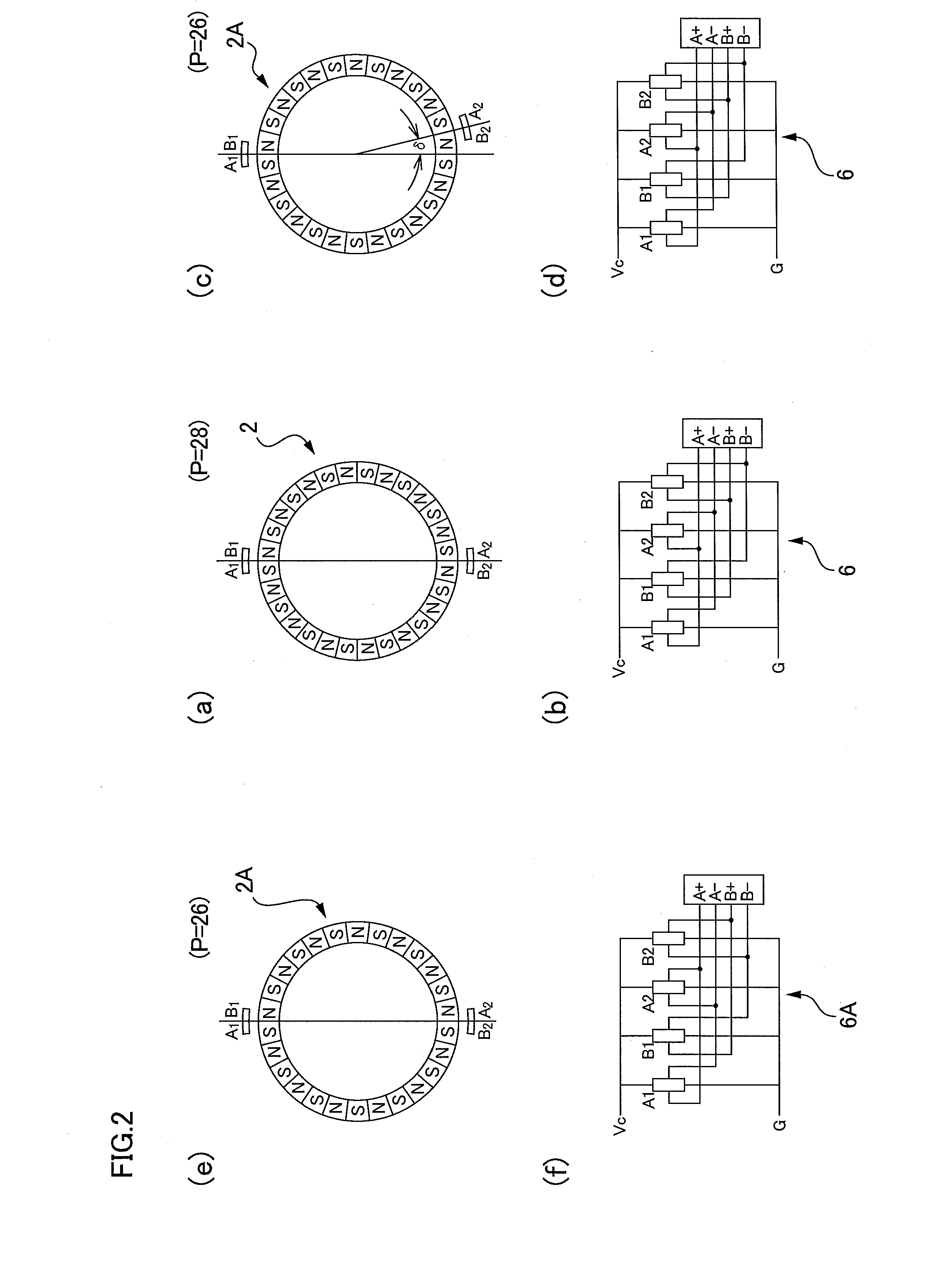
[0077]FIGS. 2(a) and 2(b) are a descriptive view ...

embodiment 2

[0085]Next, FIGS. 3(a) to3(c) are a schematic block diagram showing the magnetic encoder of embodiment 2 in which the present invention has been applied, a descriptive view showing the two-pole magnetic detecting unit of the magnetic encoder, and a descriptive view showing the multi-pole magnetic detecting unit of the magnetic encoder.

[0086]The magnetic encoder 10 has a multi-pole magnetic detecting unit 11, a two-pole magnetic detecting unit 12, and a signal processing circuit 15 for generating signals that represent the mechanical absolute position θabs within one rotation of a rotating shaft of a structure in which detection is to be carried out, e.g., a rotating shaft 14 of a servo motor 13, wherein the signals are generated on the basis of the signals obtained from the detection parts 11, 12.

[0087]The multi-pole magnetic detecting unit 11 has a multi-pole magnet 21 in which N-poles and S-poles are formed in alternating fashion at equiangular intervals along the circumferential ...

embodiment 3

[0123]Next, in the case that the number Pp of pairs of magnetic poles Pp (=P / 2) of the multi-pole magnet is an odd number and the third and fourth magnetic detection elements A2, B2 are arranged in positions separated by an electrical angle of 180° along the circumferential direction of the multi-pole magnet with respect to first and second magnetic detection elements A1, B1, the first and third magnetic detection elements A1, A2 are in positions separated by an electrical angle of 180°, and the outputs of the elements have an opposite phase. Similarly, the second and fourth magnetic detecting elements B1, B2 are also arranged in positions separated by an electrical angle of 180° and output opposite-phase sinusoidal signals. The error component produced by the magnetic flux from the two-pole magnet can be removed even with generation of an A-phase signal and a B-phase signal using the difference in the opposite-phase output signals.

[0124]In view of the above, in the multi-pole magne...


PUM


Abstract

A magnetic encoder includes a multi-pole magnetic detecting unit having a multi-pole magnet. In the multi-pole magnetic detecting unit, first and second magnetic detecting elements that output sinusoidal signals having a 90° phase difference are arranged apart from third and fourth magnetic detecting elements at a mechanical angle of 180°. The first and third magnetic detecting elements are disposed at the same position represented by an electrical angle and output sinusoidal signals of a same phase. The second and fourth magnetic detecting elements are arranged at the same position represented by an electrical angle and output sinusoidal signals of a same phase. A sum signal of the output signals of the first and third magnetic detecting elements and that of the output signals of the second and fourth magnetic detecting elements are obtained, thereby eliminating or remarkably reducing error components of detection signals of the first to fourth magnetic detecting elements caused by the magnetic flux of a two-pole magnet and those of the detection signals caused by rotational run out of the multi-pole magnet. A rotational angle can be detected with high accuracy.

Description

TECHNICAL FIELD[0001]The present invention relates to a magnetic encoder for detecting the absolute rotational position or generating an incremental signal in accompaniment with the rotation of a rotating shaft using a multi-pole magnet. The present invention particularly relates to a magnetic encoder and a method of detecting absolute rotational position capable of detecting the absolute rotational position of a rotating shaft with good precision using a multi-pole magnet and a two-pole magnet.BACKGROUND ART[0002]Magnetic encoders are used for detecting the rotational position of the rotating shaft of a servo motor or the like. Such a magnetic encoder is disclosed in, e.g., Patent Documents 1 through 3. In the position detection device disclosed in Patent Document 1, a pair of Hall elements is arranged at an angular interval of 90° so that sinusoidal signals having a phase difference of 90° are detected in accompaniment with the rotation of a bipolarly magnetized magnet ring. The e...

Claims


Application Information

Patent Timeline
IPC IPC(8): G01B7/30
CPCG01D5/2497G01D5/145G01D5/12G01D5/244G01D5/245
Inventor NAGANO, KUNIOMITAMURA, MUNEOKOYAMA, JUNJI
Owner HARMONIC DRIVE SYST IND CO LTD
Why Eureka
Try Eureka