Absolute rotary encoder and micrometer

a rotary encoder and micrometer technology, applied in the field of absolute rotary encoder and micrometer, can solve the problems reduction in measurement accuracy, etc., and achieve the effect of reducing the influence of stator or rotor displacement, preventing the intensity of the signal received at the receiving winding from lowering, and reducing the size of the absolute rotary encoder

Active Publication Date: 2008-06-10
MITUTOYO CORP
View PDF8 Cites 17 Cited by
  • Summary
  • Abstract
  • Description
  • Claims
  • Application Information

AI Technical Summary

Benefits of technology

[0008]In the absolute rotary encoder according to the present invention, each track comprises a flux coupling winding that includes linear arc portions having first and second radii and arranged alternately on the rotor and has the shape of a ring continuous about the shaft. Therefore, even if the absolute rotary encoder is downsized, it is possible to prevent the intensity of the received signal from lowering and reduce the influence from the displacement of the stator or the rotor.
[0011]In accordance with the present invention, it is possible even for a downsized absolute rotary encoder to prevent the intensity of the signal received at the receiving windings from lowering and reduce the influence from the displacement of the stator or the rotor. Therefore, an accurate, downsized absolute rotary encoder can be realized.

Problems solved by technology

Installation of the stator and the rotor into an enclosure may cause a displacement of the stator or the rotor.
Therefore, downsizing the absolute rotary encoder results in an increase in influence from the displacement and causes a reduction in measurement accuracy.

Method used


Image

  • Absolute rotary encoder and micrometer
  • Absolute rotary encoder and micrometer
  • Absolute rotary encoder and micrometer

Examples


Embodiment Construction

[0026]An absolute rotary encoder according to the embodiment will now be described with reference to the drawings (hereinafter the “absolute rotary encoder” may also be referred to as the “encoder”). In the figures, the same parts as those denoted with the reference numerals in the figure once described are given the same reference numerals and omitted from the following description.

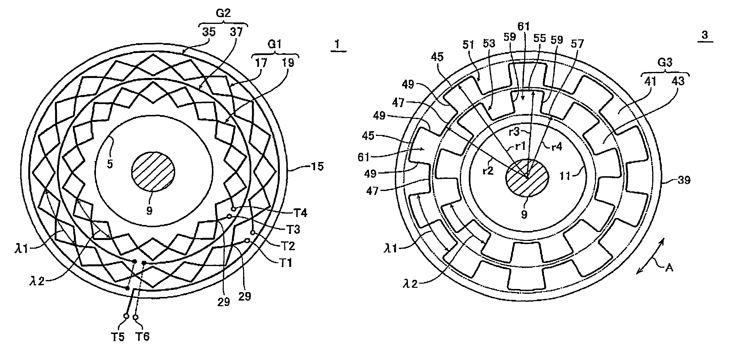
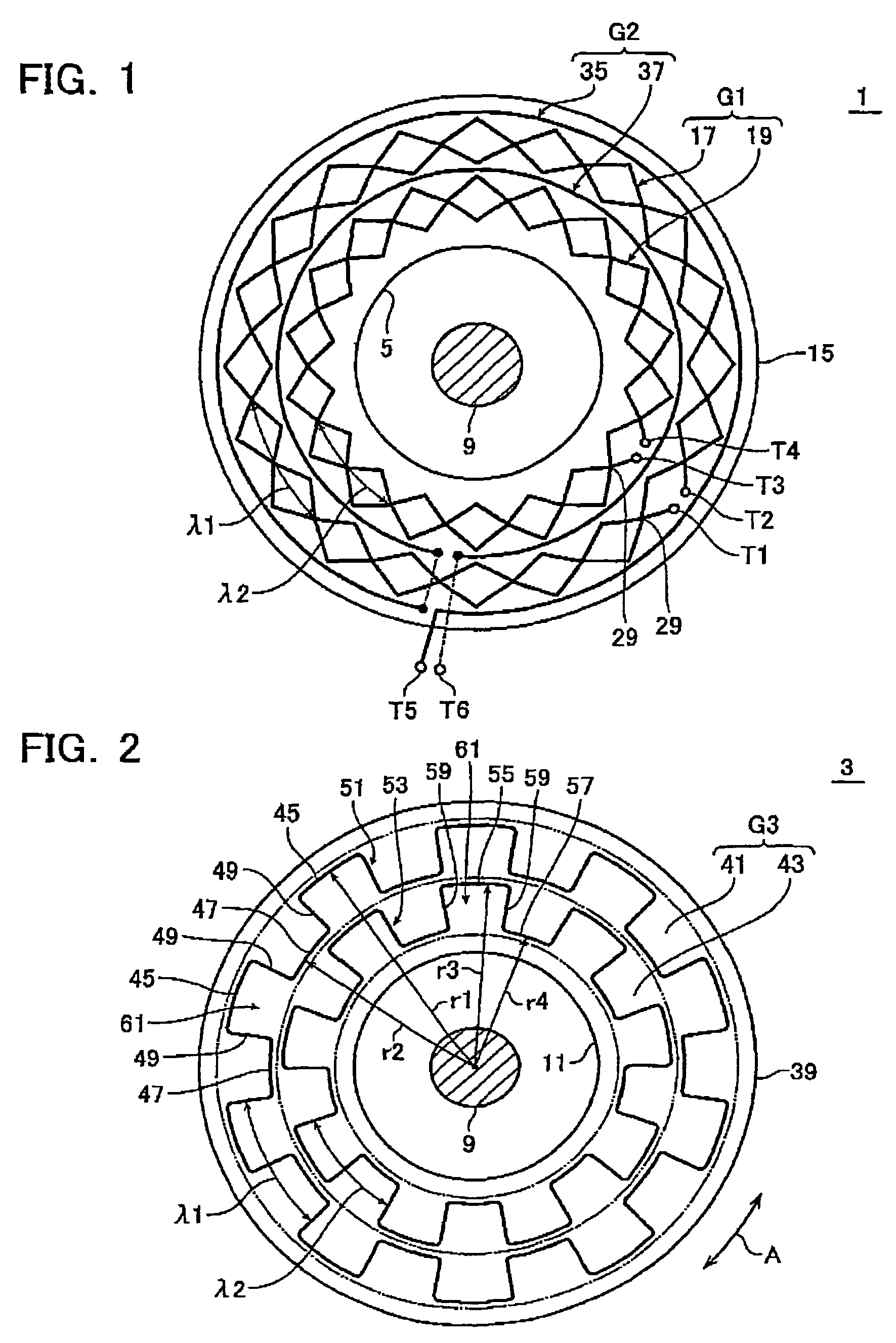
[0027]FIG. 1 is a plan view of a stator 1, which is a component of the absolute rotary encoder according to the embodiment, and FIG. 2 is a plan view of a rotor 3. The stator 1 has a bore 5 formed through the center, and a shaft 9 passes through the bore 5. The rotor 3 also has a bore 11 through the center to receive the shaft 9 therein. The rotor 3 is arranged about the shaft 9 rotatably in the direction of the arrow A, interposing a rotor bush, not shown, fitted in the bore 11 therebetween, and opposite the stator 1. The stator 1 and the rotor 3 are composed of a printed circuit board, a glass substrat...


PUM

PropertyMeasurementUnit
radiiaaaaaaaaaa
radiiaaaaaaaaaa
radiiaaaaaaaaaa

Abstract

An absolute rotary encoder comprises a rotor having a bore passing through the center thereof to receive a shaft therein and arranged rotatably about the shaft and opposite a stator. Tracks are arranged concentrically on the rotor to form a track group. A transmitting winding group is arranged on the stator as capable of flux coupling with the track group. A receiving winding group is arranged on the stator as capable of flux coupling with the track group. Each track in the track group comprises a flux coupling winding that includes linear arc portions having first and second radii and arranged alternately on the rotor and has the shape of a ring continuous about the shaft. At least two tracks in the track group have the linear arc portions different in number from each other.

Description

CROSS REFERENCE TO RELATED APPLICATION[0001]This application is based on and claims the benefit of priority from prior Japanese Patent Application No. 2005-120819, filed on Apr. 19, 2005, the entire contents of which are incorporated herein by reference.BACKGROUND OF THE INVENTION[0002]1. Field of the Invention[0003]The present invention relates to an absolute rotary encoder operative to measure displacements through the use of flux coupling, and a micrometer including the encoder mounted thereon.[0004]2. Description of the Related Art[0005]A rotary encoder comprises a stat or having transmitting windings and receiving windings arranged thereon, and a rotor having tracks arranged thereon as capable of flux coupling with these windings. Such the encoder includes the absolute type as disclosed in JP-A 10-213407 (FIGS. 2 and 3) and U.S. Pat. No. 3,812,481 (column 5, line 68 to column 6, line 3; column 7, lines 31-35; FIGS. 1 and 2). In particular, the latter discloses a relatively larg...

Claims


Application Information

Patent Timeline
Patent Type & Authority Patents(United States)
IPC IPC(8): G01B7/30H01F5/00
CPCG01D5/2086G01D5/24438G01D5/2452
Inventor TAHARA, TOMOHIROTSUJI, SHOZABURO
Owner MITUTOYO CORP
Why Eureka
Try Eureka