Hair curling apparatus and hair curling method

A technology for curling hair and utensils, applied in curling or perm devices, hairdressing equipment, clothing, etc., can solve the problem of beautiful curly hair, and achieve the effect of strong curly correction

Inactive Publication Date: 2005-12-14
木俣 年博 +1
View PDF0 Cites 12 Cited by
  • Summary
  • Abstract
  • Description
  • Claims
  • Application Information

AI Technical Summary

Problems solved by technology

That is, the hair cannot be all curled beautifully

Method used


Image

  • Hair curling apparatus and hair curling method
  • Hair curling apparatus and hair curling method
  • Hair curling apparatus and hair curling method

Examples


Embodiment Construction

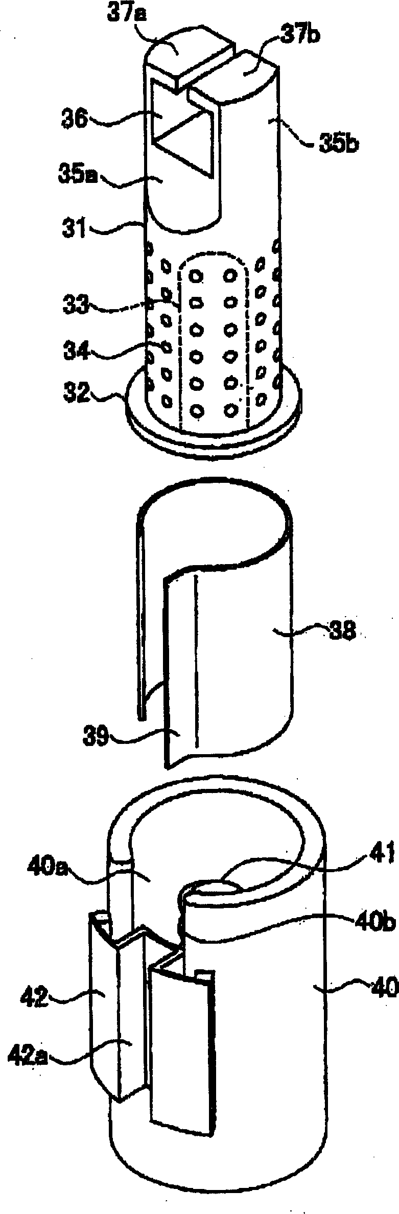
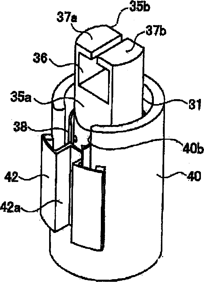
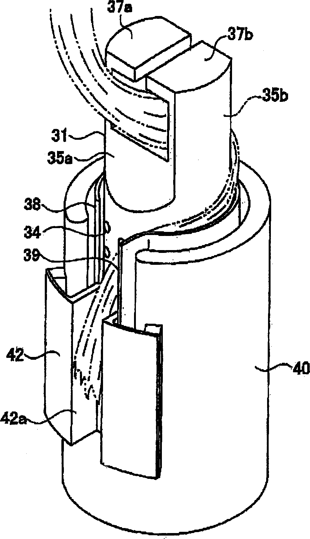
[0044] Figure 1 to Figure 4 It is the curling appliance of the first embodiment of the present invention, wherein figure 1 is a three-dimensional view of the exploded state, figure 2 is a three-dimensional diagram of the combined state, image 3 For the three-dimensional figure in the curling of the hair, Figure 4 It is a three-dimensional image after curling.

[0045] In the accompanying drawings, the following reference signs represent respectively:

[0046]1~shaft body; 1a~head; 1b~body; 2~elastic suspension piece; 3~guiding groove; 4~screw groove; 5~cylindrical body; 6~screw groove; ~cover body; 9~comb teeth; 11~roller body; 12~ring body; 12a~stopper; 13a~roller; 13b~roller; 31~shaft body; Hole; 34~hole; 35a, 35b~flat face; 36~concavity; 37a, 37b~flip type opening and closing window; 38~stopper; 38'~stopper; 39~upright piece; 40~cylindrical body ; 40a ~ opening; 40b ~ wall; 41 ~ screw shaft; 42 ~ guide member; 42a ~ concave section; 50 ~ spacer;

[0047] In each...


PUM


Abstract

A curling appliance for curling hair, comprising: a shaft body for curling hair; a detachably arranged stopper with a slightly C-shaped cross-section on the outside of the shaft body; arranged on the outside of the stopper, and A screwing device screwed to the shaft body, wherein by rotating the screwing device in a state where the root side of the hair stays on the shaft body and the front side of the hair is guided to the screwing device side, The hair is curled in a helical shape by the rotation of the shaft. The present invention provides a hair curling technique that makes hair curl beautifully but has excellent workability.

Description

technical field [0001] The present invention relates to a technique for curling hair. Background technique [0002] Curling appliances for curling hair are already on the market. This hair curler is Figure 13 As shown, it is composed of a plastic cylinder, and its use is as follows. First, the front end of the hair is pressed against the surface of the cylindrical body W, and the hair is curled on the cylindrical body W from the front end side. Then, after curling to the root side of the hair, a stopper is attached so that the hair does not loosen. After that, its state is temporarily maintained. In this way, even if loosened, the hair becomes curled along the shape of the cylindrical body W. [0003] then, use Figure 13 In the case where the illustrated curling iron curls the hair, the curl is often unsightly. [0004] Also curl assignments are cumbersome. [0005] Then, the inventor of the present invention explained the reason why the hair cannot be curled beautif...

Claims


Application Information

Patent Timeline
Patent Type & Authority Applications(China)
IPC IPC(8): A45D2/00
Inventor 木俣年博大竹诚
Owner 木俣 年博
Why Eureka
Try Eureka