Tableware cleaning machine

A tableware washing machine and washing water technology, applied in the direction of tableware washing machine/rinsing machine, tableware washing machine/rinsing and rinsing machine parts, cleaning equipment, etc., can solve the problem of dissolution

Active Publication Date: 2005-12-14
PANASONIC CORP
View PDF1 Cites 5 Cited by
  • Summary
  • Abstract
  • Description
  • Claims
  • Application Information

AI Technical Summary

Problems solved by technology

However, if the oscillator is still vibrating when the atomization surface is exposed to the surface of the cleaning water, the atomization surface may self-heat due to ultrasonic vibration, and sometimes it may dissolve.

Method used


Image

  • Tableware cleaning machine
  • Tableware cleaning machine
  • Tableware cleaning machine

Examples


Embodiment Construction

[0012] Embodiments of the present invention will be described in detail below with reference to the accompanying drawings. It should be noted that such embodiments do not limit the technical scope of the present invention.

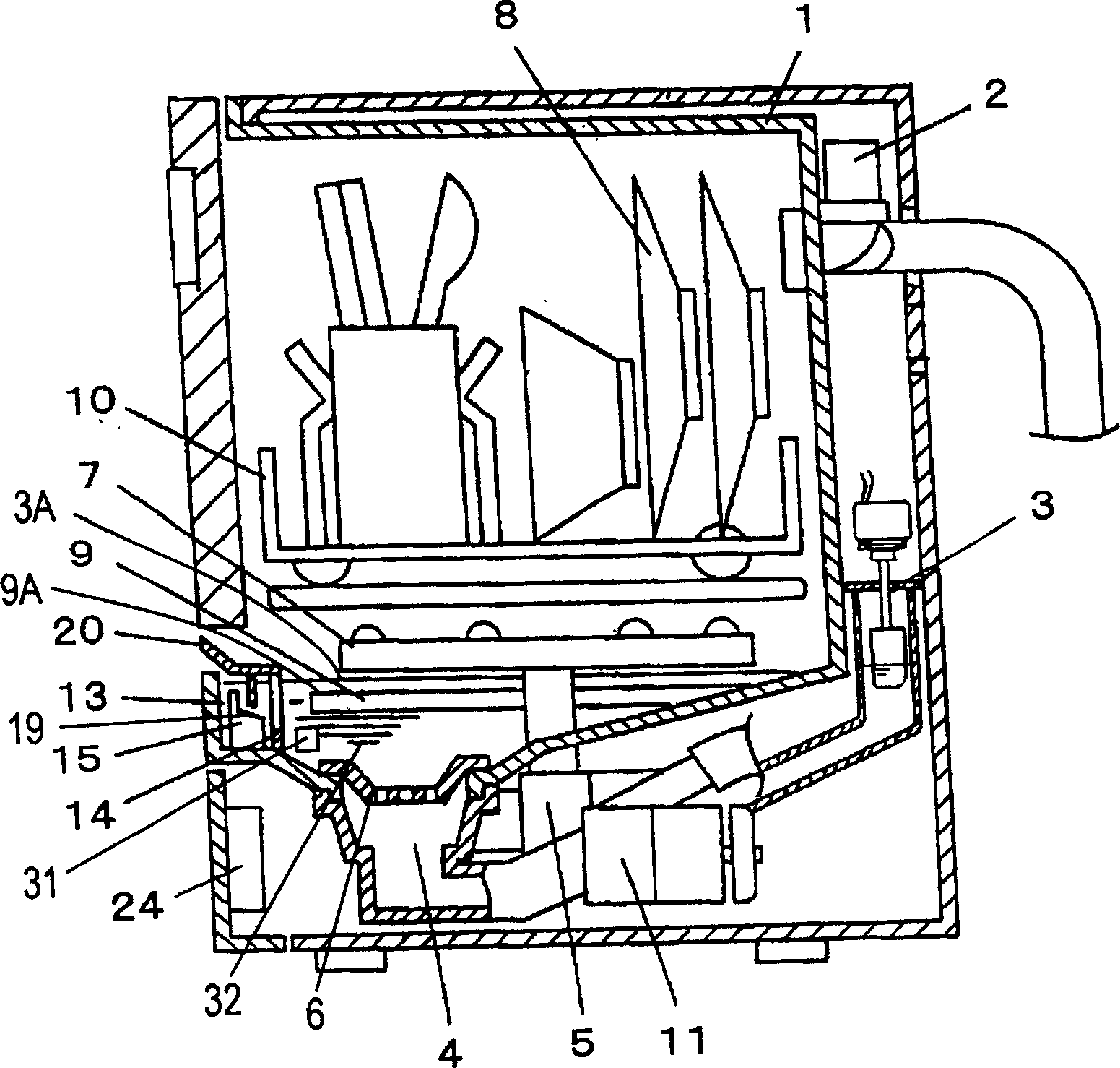
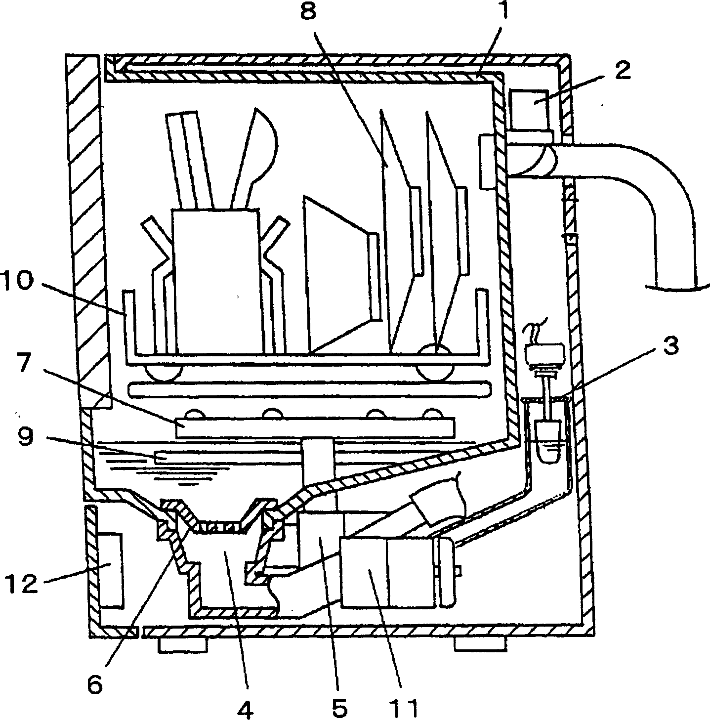
[0013] figure 1 It is a longitudinal sectional view of the dishwasher which is one Example of this invention. Wherein, tableware and other objects to be cleaned 8 are loaded into the cleaning tank 1 , and a water inlet device (water inlet valve) 2 is used for adding water to the cleaning tank 1 . The added water can be normal temperature water or hot water. The water level detection device 3 is used to detect the water level in the cleaning tank 1, and when the water level reaches a specified water level, the control device 24 stops the water inlet device 2 from feeding water. The bottom of the cleaning tank 1 is provided with a drainage hole 4, and the drainage hole 4 communicates with a cleaning pump 5 driven by an electric motor. The washing pump 5...


PUM


Abstract

PROBLEM TO BE SOLVED: To provide a dishwasher with significantly improved convenience for washing objects to be washed such as tableware by spraying washing water. SOLUTION: The dishwasher comprises a mist generating means 15 for misting a detergent liquid inside a washing tub 1, a water level detecting means 3 for detecting the water level inside the washing tub 1, and a control means 24 for receiving signals from the water level detecting means 3 and controlling the motion of each load. The control means 24 drives the mist generating means 15 when the water level detecting means 3 detects the water level. COPYRIGHT: (C)2006,JPO&NCIPI

Description

technical field [0001] The present invention relates to a dish washer which cleans objects to be cleaned such as tableware by spraying washing water. Background technique [0002] image 3 It is a sectional view of a conventional dishwasher disclosed in Japanese Patent Laid-Open No. 2003-210378. Wherein, the objects to be cleaned such as tableware to be cleaned 8 are put into the cleaning tank 1 , and the water inlet device (water inlet valve) 2 is used for supplying water to the cleaning tank 1 . Here, it is also possible to use hot water. The water level detection device 3 detects the water level in the cleaning tank 1, and when it reaches a specified water level, the water inlet device 2 is automatically stopped from feeding water. The bottom of the cleaning tank 1 is provided with a drain hole 4 , and a cleaning pump 5 driven by a motor is installed to communicate with the drain hole 4 . Under the action of the cleaning pump 5 , water circulates inside the cleaning ta...

Claims


Application Information

Patent Timeline
Patent Type & Authority Applications(China)
IPC IPC(8): A47L15/13A47L15/42A47L15/46
CPCA47L15/4244A47L15/4287A47L15/4436
Inventor 田中淳裕角谷胜彦谷口裕
Owner PANASONIC CORP
Why Eureka
Try Eureka