Rotary atomizer system

A rotary atomizer and rotary atomization technology, applied in the field of atomizers, can solve the problem of uneven distribution of material and liquid, and achieve the effects of increasing the thickness of one side, improving the service life, and facilitating collection.

Pending Publication Date: 2018-07-20
ANHUI XINCHUANG ENERGY SAVING & ENVIRONMENTAL PROTECTION SCI & TECH +1
View PDF8 Cites 3 Cited by
  • Summary
  • Abstract
  • Description
  • Claims
  • Application Information

AI Technical Summary

Problems solved by technology

[0006] The purpose of the present invention is to overcome the shortcomings of serious atomizer wear and uneven distribution of material and liquid in the prior art, and provide a rotary atomizer system that can ensure that the material and liquid are evenly distributed into the discharge pipe and the atomization wheel, so that the fog Uniform atomization, the nozzle is not easy to block, and the service life of the high-speed rotary atomizer is improved

Method used


Image

  • Rotary atomizer system
  • Rotary atomizer system
  • Rotary atomizer system

Examples


Embodiment 1

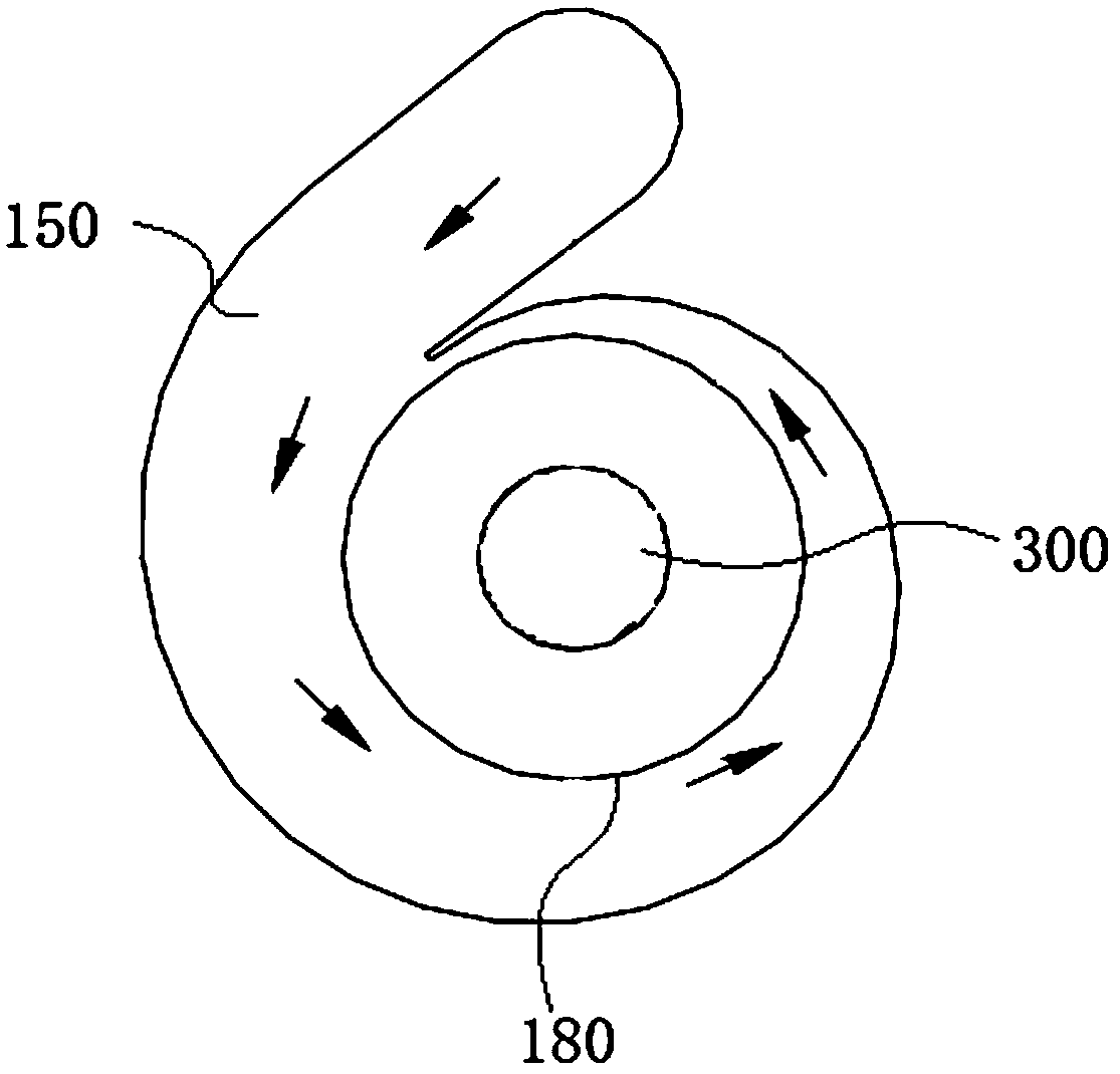
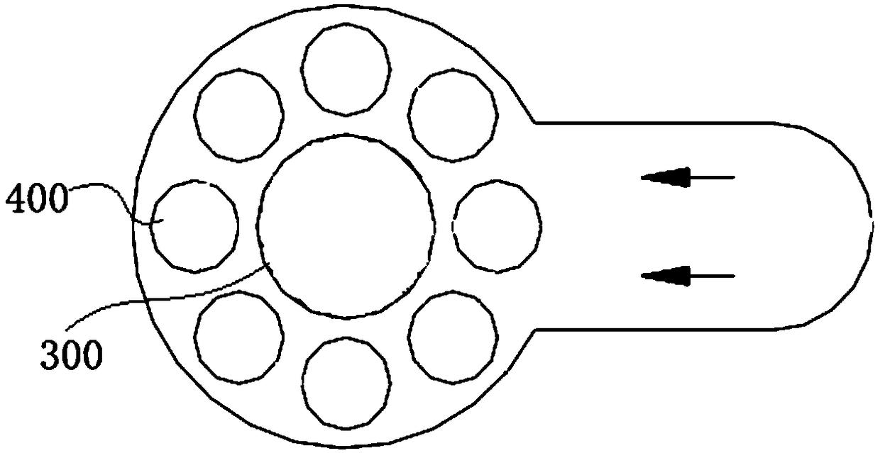
[0050] Such as image 3 As shown, a rotary atomizer system in this embodiment includes a feed liquid distributor 100, a rotary atomizer wheel 200 and a rotary spindle 300, wherein the discharge pipe 180 of the feed liquid distributor 100 corresponds to the rotary atomizer wheel 200 The atomizing wheel inlet 210, the material-liquid distributor 100 and the top plate 110 are connected to the base of the rotating main shaft 300 on the top of the top plate 110 by bolts. Such as figure 1 and figure 2 Shown is the conventional design structure of the feed-liquid distributor 100 in the high-speed rotary dry atomizer in the prior art, and the design adopts the volute type respectively (see figure 1 ) and orifice plate (see figure 2 )structure. The size of the involute of the volute material-liquid distributor is determined according to the design flow. When the design flow is running, the flow rate of the material and liquid in each section of the involute is uniform, and it is ...

Embodiment 2

[0059] A kind of rotary atomizer system of this embodiment, the basic structure is the same as that of Embodiment 1, the difference is that in this embodiment, α=30°, the oblique setting of multiple guide vanes 181 makes it in the discharge pipe 180 The inner wall is helically distributed as a whole, which can evenly divide the incoming material liquid and produce a pre-swirl effect on the flow of the material liquid, so that the material liquid enters the rotating atomizing wheel 200 at a tangential angle, and the inclination angle of the guide vane 2 181 is set to conform to the rotation The rotation direction of the atomizing wheel 200 makes it easier for the feed liquid to enter the nozzle 230 , which can further improve the service life of the rotating atomizing wheel 200 , and ultimately ensure the smooth operation of the rotating atomizing wheel 200 and the rotating spindle 300 .

Embodiment 3

[0061] A rotary atomizer system in this embodiment has the same basic structure as that in Embodiment 2, except that α=45° in this embodiment.


PUM


Abstract

The invention discloses a rotary atomizer system, and belongs to the technical field of atomizers. The system comprises a feed liquid distributor, a rotary atomizing wheel and a rotary main shaft, wherein the discharge pipe of the feed liquid distributor corresponds to the atomizing wheel inlet of the rotary atomizing wheel, and second guiding blades are uniformly arranged in the circumferential direction of the inner wall of the discharge pipe at intervals; a nozzle is arranged at the atomizing wheel outlet of the rotary atomizing wheel, an inlet hole is formed in the inner circle inlet section of the nozzle, and the inlet hole is an eccentric variable-diameter hole. The invention aims at overcoming the defects of severe abrasion and nonuniform distribution of feed liquid of atomizers inthe prior art, and provides the rotary atomizer system; the system can ensure that the feed liquid enters the discharge pipe and the atomizing wheel with uniform distribution, so that the feed liquidis atomized uniformly, the nozzle is not easily blocked, and the service life of the atomizer is prolonged.

Description

technical field [0001] The present invention relates to the technical field of atomizers, and more specifically, relates to a rotary atomizer system. Background technique [0002] At present, most of the material-liquid distributors of high-speed rotary drying atomizers at home and abroad are designed with volute type and orifice type structure. When the volute-type material-liquid distributor is running at the designed flow rate, the flow velocity of the material liquid in each section of the volute is balanced, and the distribution is even when entering the discharge pipe. At the same time, the radial force from the material liquid on the spindle is balanced. When the flow rate of the material liquid deviates from the design flow rate, the flow velocity of each section is not equal, resulting in uneven distribution of the material liquid entering the discharge pipe and even blockage of the material liquid. The structure of the orifice-type feed-liquid distributor is simpl...

Claims


Application Information

Patent Timeline
Patent Type & Authority Applications(China)
IPC IPC(8): B05B3/10B05B9/03
CPCB05B3/1007B05B9/03
Inventor 吴海彤方健陈东陈锋倪红兵
Owner ANHUI XINCHUANG ENERGY SAVING & ENVIRONMENTAL PROTECTION SCI & TECH
Why Eureka
Try Eureka