
Liquid tube for electrohydraulic chip

A chip and liquid pipe technology, applied in the field of liquid pipes for electro-hydraulic chips, can solve the problems of difficulty in production and assembly, limit output, increase costs, etc., and achieve simple and easy production and assembly, reduce production costs, and reduce flow resistance. Effect

Inactive Publication Date: 2005-12-21
陈城书 +1
View PDF1 Cites 0 Cited by
  • Summary
  • Abstract
  • Description
  • Claims
  • Application Information

AI Technical Summary

Problems solved by technology

Since the existing technology is to have a conical spring at both ends of the tube core to support the tube core, the elasticity of the two conical springs must be the same, which brings difficulties to production and assembly, and limits the output. increased costs

Method used


Image

  • Liquid tube for electrohydraulic chip
  • Liquid tube for electrohydraulic chip

Examples


Embodiment Construction

[0009] In order to clearly illustrate the technical features of the solution, the solution will be described below through a specific implementation.

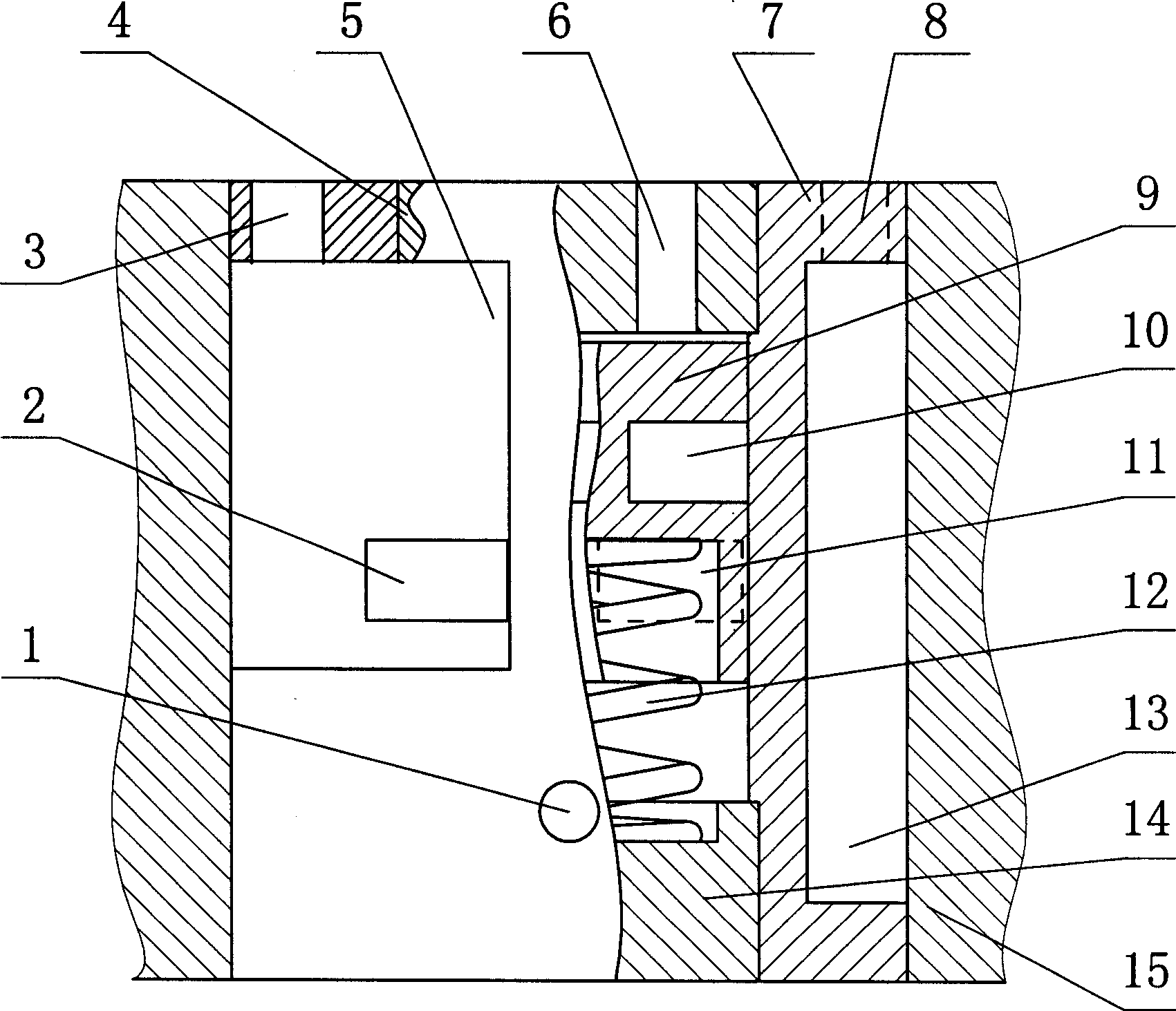
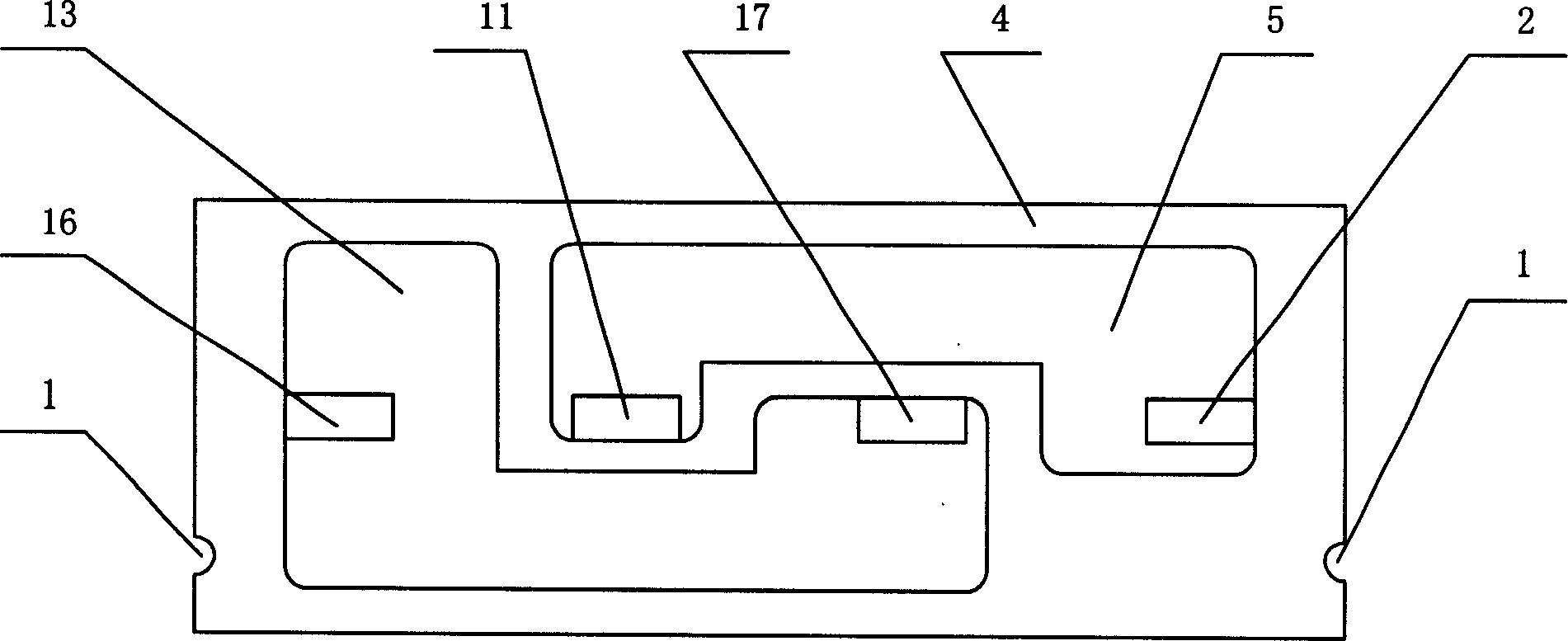
[0010] As can be seen from the accompanying drawings, the liquid pipe for the electro-hydraulic chip of this program has a chip substrate (15), and a cylindrical hollow tube sleeve (7) is arranged in the chip substrate (15), and on the inner cavity of the tube sleeve (7) There is an upper cover plate (4) on the top surface, and a lower cover plate (14) on the lower top surface, and there is a tube core ring groove (10) in the cavity between the upper cover plate (4) and the lower cover plate (14). ) of the die (9). This scheme is that there is an upper control oil passage (6) on the upper cover plate (4), which communicates with the inner cavity of the pipe sleeve (7) on the top of the pipe core (9), and there is a lower control oil passage ( 1) It communicates with the inner cavity of the pipe sleeve (7) at the bottom of the ...


PUM


Abstract

This technical plan is characterized in that in the upper lid plate there is an upper control oil-line communicated with the sleeve tube inner room at the top part of the tube core; at the lower part of the sleeve tube there is a lower control oil-circuit communicated with the inner room of the sleeve tube at the tube core. At the bottom of the tube core there is a spring for supporting the tube core. On outer wall of the sleeve tube there are left and right oil tanks which are not communicated each other, in which the left oil tank is communicated with the left controlled oil circuit and the right oil tank is communicated with the right controlled oil circuit. On the left and the right oil tank there are two oil holes which are on same plane and not opposite each other and the four oil holes are all communicated with the ring slot on the tube core.

Description

Technical field: [0001] The invention relates to a hydraulic component, in particular to a liquid pipe for an electro-hydraulic chip. Background technique: [0002] In the prior art, the prior art closest to the present invention is Chinese Patent No. 85102444 invented by myself, which discloses a hydraulically controlled electro-hydraulic integrated block, which discloses a hydraulically controlled two-way valve. The valve has a conical spring at the upper and lower ends of the tube core to support the tube core. The control oil channel is input from the upper and lower ends of the tube core. When there is a pressure difference between the two ends of the control oil channel, the tube core will move up and down. , to open or close the four oil holes on the pipe sleeve, thereby controlling the controlled oil passage, and amplifying the small pressure change. Since the existing technology is to have a conical spring at both ends of the tube core to support the tube core, the...

Claims


Application Information

Patent Timeline
IPC IPC(8): F15B13/00
Inventor 陈城书陈博文
Owner 陈城书
Learn More