Quick connection terminal device

A technology for quick connection and equipment, which is applied in the direction of connection, clamping/spring connection, and parts of the connection device. It can solve the problems of changing the main body of the equipment, increasing the number of parts, and increasing the cost, so as to increase the contact area and touch the operating part. prevent effect

Inactive Publication Date: 2005-12-28
MATSUSHITA ELECTRIC WORKS LTD
View PDF0 Cites 29 Cited by
  • Summary
  • Abstract
  • Description
  • Claims
  • Application Information

AI Technical Summary

Problems solved by technology

[0005] However, in the conventional wire connection completion display mechanism, since it is necessary to newly add two components, the display member H2 and the coil spring H3, and to form a space for accommodating these two components in the main body of the device, there is a problem that The increase in the number of parts and the change in the design of the main body of the device lead to an increase in cost
Also, in the conventional mechanism, since the wire connection completion is visually displayed, there is a problem that it cannot be externally determined whether the wire connection is completed when the display part is invisible

Method used


Image

  • Quick connection terminal device
  • Quick connection terminal device
  • Quick connection terminal device

Examples


no. 1 approach

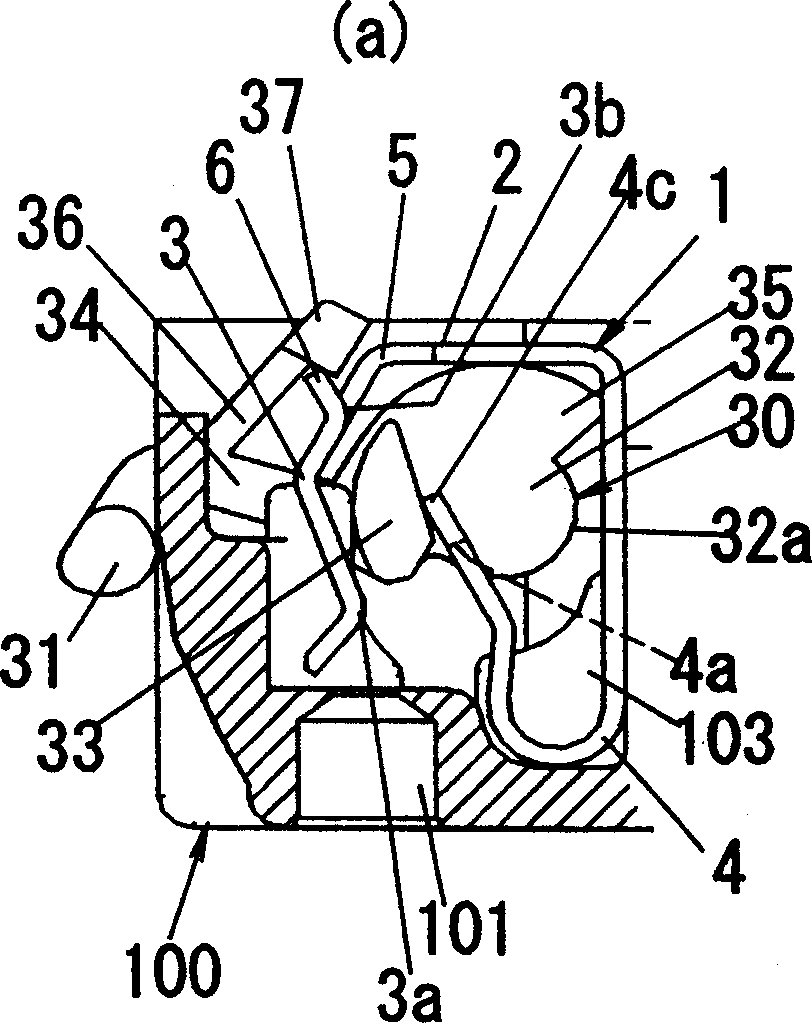
[0097] The quick connect terminal device according to this embodiment includes such as Figure 1 to Figure 3 Terminal strip 1 and release lever 30 are shown. Such as figure 2 As shown, the terminal board 1 has: a rectangular main piece 2; a pair of contact pieces 3 extending vertically downward from one edge of the main piece 2 along its longitudinal direction; A pair of J-shaped locking pieces 4 extending vertically downwards along its longitudinal direction. The main piece 2, the contact piece 3 and the locking piece 4 are integrally formed by processing a strip-shaped elastic metal plate, so that the front ends of the contact piece 3 and the locking piece 4 cross each other. Each contact piece 3 has: a pair of pressing parts 3a and 3b that press the two ends of the wire along the insertion direction of the wire; a hook-shaped part 6 formed by bending the front end of the upper pressing part 3b in the direction away from the locking piece 4; And the opening 5 for passing...

no. 2 approach

[0105] now refer to Figures 5 to 13 The quick connect terminal device according to the present embodiment will be described. Components common to the first embodiment are denoted by the same reference numerals, and description and illustration thereof are appropriately omitted.

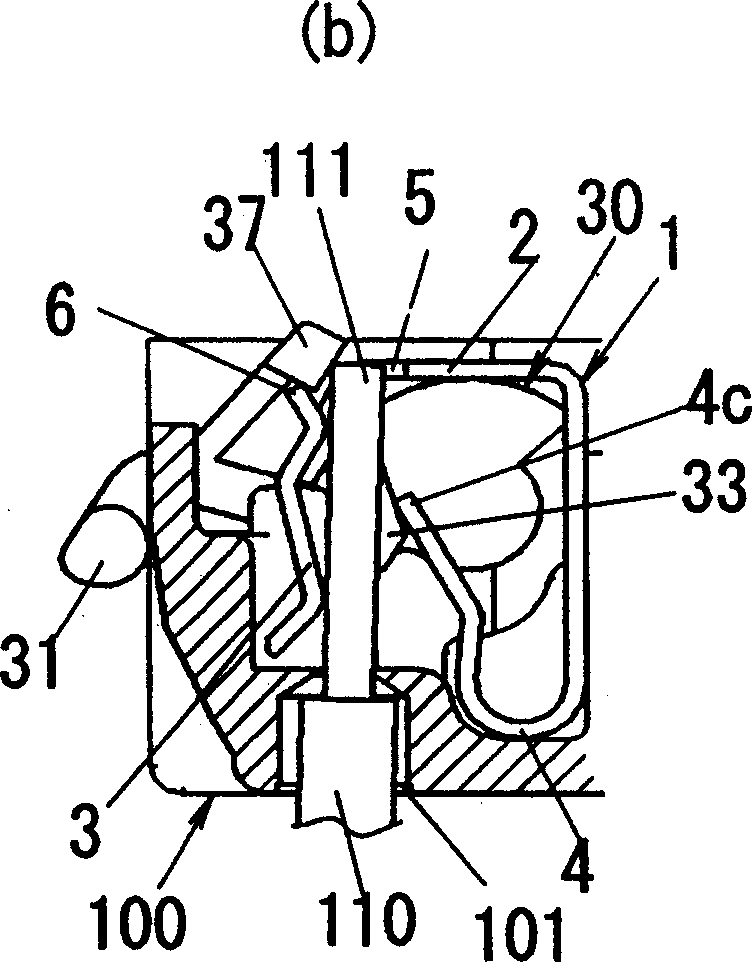
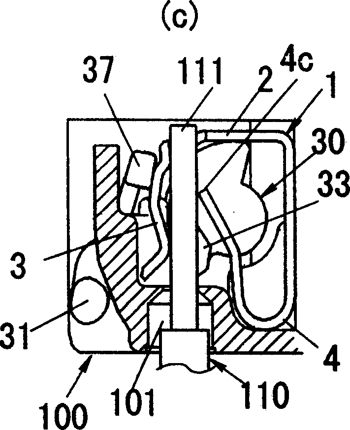
[0106] In the terminal board 1 according to the present embodiment, as Figure 5 and Figure 6 As shown, the contact piece 3 is roughly in the direction perpendicular to the insertion direction of the wire 110 ( Figure 5 centered in the left-right direction) and two parts other than the central part of the locking part 4a are taken as the receiving part 4c.

[0107] On the other hand, if Figure 7 and Figure 8 As shown, the release lever 30 according to this embodiment includes a second pressing and moving portion 38 opposite to the pressing and moving portion 33, wherein the contact piece 3 is interposed between the pressing and moving portion 33 and the second pressing and moving portion 38;...

no. 3 approach

[0112] Although the connection structure between the terminal board 1 and other conductive members (the contact point of the switch or the knife-edge support of the electrical socket) is not particularly described in the first and second embodiments, it is preferable that the terminal board 1 and other conductive members be processed Formed integrally from sheet metal. However, in the first and second embodiments, since the terminal plate and the lock spring are integrally formed, a mold with a very complicated shape is required to integrate the additional conductive member. In order to avoid complicated molds, the terminal board and the other conductive members should be connected using caulking or welding methods.

[0113] Therefore, in this embodiment, if Figure 14 (a) and Figure 15 As shown, the connection device is formed by removing the locking piece 4 from the terminal board 1 and forming a connection device with a locking spring 10 having a U-shaped spring piece 10...


PUM


Abstract

There is provided a quick connection terminal device which can visually and auditively display the connecting completion of a wire and which can suppress increase in the number of components. When the connection of a wire 110 to a terminal plate 1 is completed, a manipulation portion 31 of a release lever 30 is moved downward from an initial position, whereby it is possible to visually display the connecting completion of the wire. In addition, it is possible to display the connecting completion of the wire with sound (collision sound) generated when the manipulation portion 31 collides with the surface of a device body 100. Furthermore, by using the release lever 30 for cutting off the connection of the wire 110 in common to display the connecting completion of the wire 110, it is possible to suppress increase in the number of components.

Description

technical field [0001] The invention relates to a quick connection terminal device. Background technique [0002] Conventionally, wiring mechanisms such as electric switches and electric sockets widely use quick-connect terminal devices for connecting wires inserted into a device body through wire insertion holes formed in the device body. This type of quick-connect terminal device is well known and includes: a terminal block electrically connected to the switch contacts; a knife-edge bearing or similar structure for an electrical socket; a locking spring that clamps and supporting wires (conductors), cooperating with the terminal board to electrically connect the wires to the terminal board, and fixing the wires so as to prevent the wires from falling out; Operate and release the fixation with the lock spring (for example, see Patent Document 1). [0003] However, in the conventional quick-connect terminal device, since it cannot be seen from the outside whether the wire ...

Claims


Application Information

Patent Timeline
Patent Type & Authority Applications(China)
IPC IPC(8): H01R4/48
CPCH01R13/635H01R13/639H01R13/641
Inventor 本田稔近藤真树桥本昇加藤一祐岛冈国康
Owner MATSUSHITA ELECTRIC WORKS LTD
Why Eureka
Try Eureka