Tire with rotation period indication hole, and method of indicating tire rotation period

一种时间指示、轮胎胎面的技术,应用在轮胎胎面/胎面花纹、轮胎测量、轮胎零部件等方向,能够解决错过换位时间、难识别台阶部等问题,达到经济有效使用的效果

Inactive Publication Date: 2005-12-28
SUMITOMO RUBBER IND LTD
View PDF4 Cites 4 Cited by
  • Summary
  • Abstract
  • Description
  • Claims
  • Application Information

AI Technical Summary

Problems solved by technology

[0005] However, since the hole shape of these conventional indicating holes is either a circular hole or a square hole, it is difficult to identify the step portion by visual inspection, and there is a risk of missing the appropriate transposition time.

Method used


Image

  • Tire with rotation period indication hole, and method of indicating tire rotation period
  • Tire with rotation period indication hole, and method of indicating tire rotation period
  • Tire with rotation period indication hole, and method of indicating tire rotation period

Examples


Embodiment Construction

[0027] Hereinafter, embodiments of the present invention will be described with reference to the drawings.

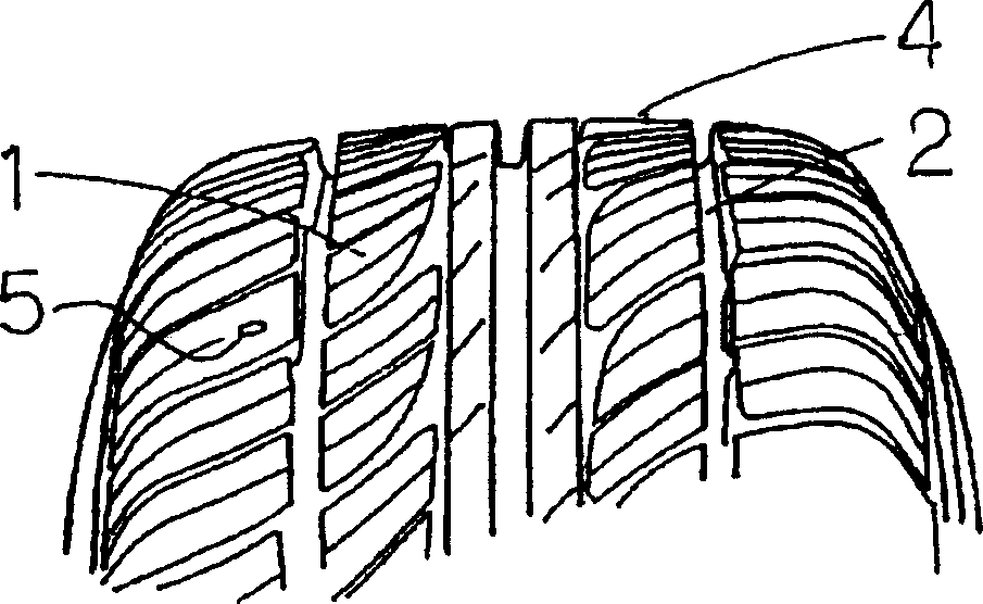
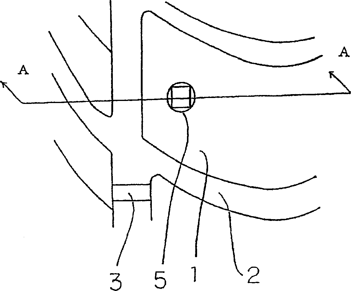
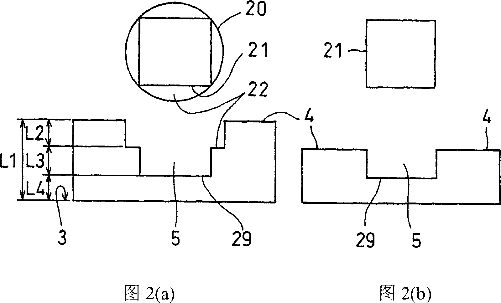
[0028] Fig. 1, Fig. 2 represent the embodiment of the tire with the transposition time indication hole of the present invention.

[0029] FIG. 1( a ) is a tire perspective view showing a tire tread portion 1 and a sipe 2 . FIG. 1( b ) is a partially enlarged view of FIG. 1( a ), showing a wear indicator 3 protruding from a tire groove 2 and one of the transposition time indicating holes 5 provided near the wear indicator 3 . The wear indicator 3 is used to indicate that the wear of the tire has reached a safety limit and should be replaced with a new one. The transposition time indication hole 5 is used to represent the sign indicating the transposition time for changing the tire installation position according to the degree of tire wear. The shift time indicating hole 5 passes through the tread portion 4 of the tire tread 1 inwardly in the tire radial direction.

[...


PUM


Abstract

The tire with the transposition time indicating hole of the present invention is provided with a transposition time indicating hole composed of multiple stepped holes on the tire tread, and the profiles and shapes of the above-mentioned stepped holes are different. The tire rotation time can be known from the change in the contour shape of the hole due to tire wear.

Description

technical field [0001] The present invention relates to a vehicle tire provided with an indicator capable of notifying the timing of tire rotation. Background technique [0002] In order to prolong the service life of tires mounted on vehicles, the so-called transposition (position exchange: rotation) method has been adopted, that is, the mounting position of the tires on the vehicle is changed according to the progress of tire tread (tire surface) wear. [0003] As a tire with a tread wear indicator capable of indicating such a transposition time, there are, for example, Japanese Patent Laid-Open No. 55-110608, Japanese Utility Model Laid-Open No. 59-25684, and International Publication No. WO97. / 47483 (JP-A-10-511626) and the like are already known. [0004] In the conventional technologies, a multi-step hole is provided on the tire tread as an indication hole for the time of rotation. If the first step of the hole disappears due to wear, it is ...

Claims


Application Information

Patent Timeline
Patent Type & Authority Applications(China)
IPC IPC(8): B60C11/24
CPCB60C11/24Y10T152/10027
Inventor 藤井谦作村田雄彦
Owner SUMITOMO RUBBER IND LTD
Why Eureka
Try Eureka