Water flow automatic control method for mixed water heater

A water heater and hybrid technology, applied in the field of automatic water flow control of hybrid water heaters, can solve the problems of short life, high cost of water tanks, and inability to realize central water supply, etc., and achieve the effects of long life, simple structure, and low pressure value

Inactive Publication Date: 2006-01-04
麦广海
View PDF2 Cites 1 Cited by
  • Summary
  • Abstract
  • Description
  • Claims
  • Application Information

AI Technical Summary

Problems solved by technology

[0003] The purpose of the present invention is to solve the problems of high cost and short service life of the water tank in the current control method of the water flow of the closed water storage water heater or the problem that the central water supply cannot be realized in the current control method of the water flow of the open water heater, and provide A water flow automatic control method of a hybrid water heater with simple structure, convenient use and long service life

Method used


Image

  • Water flow automatic control method for mixed water heater
  • Water flow automatic control method for mixed water heater
  • Water flow automatic control method for mixed water heater

Examples


Embodiment 1

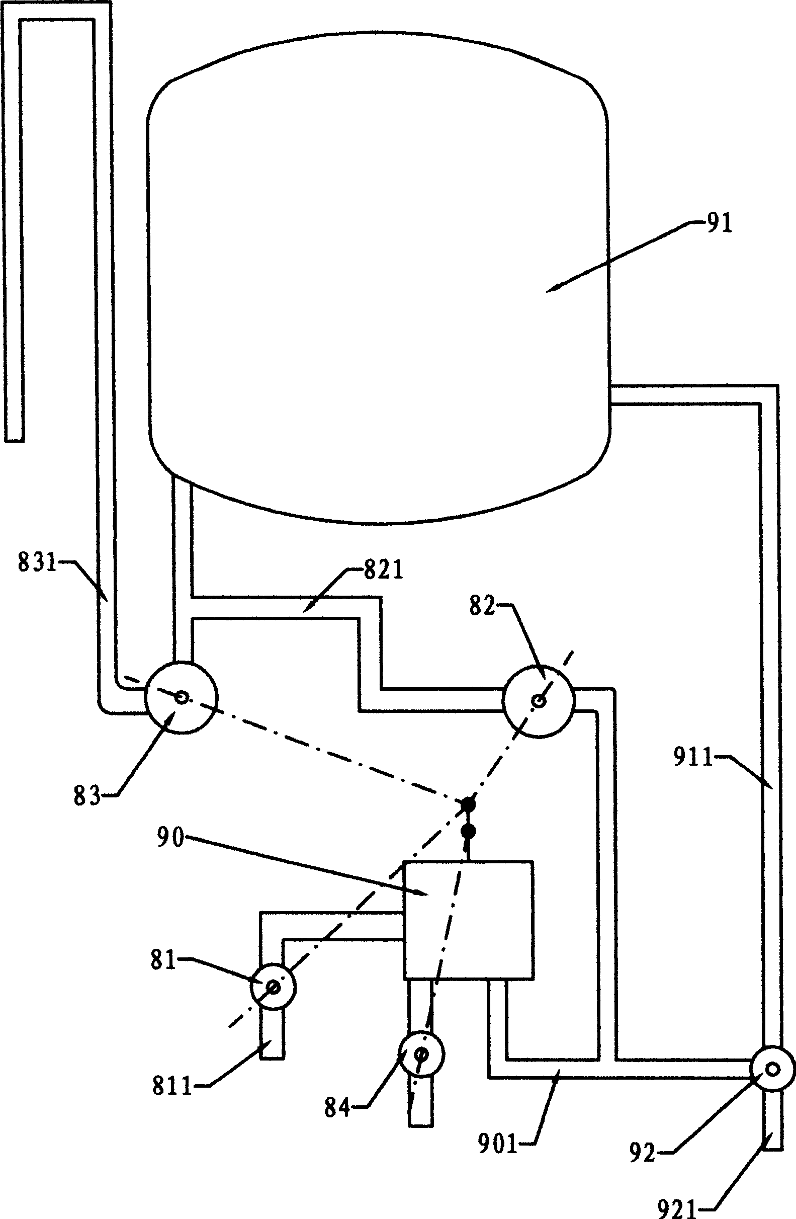
[0047] Embodiment one, see figure 1 , the automatic water flow control method of the hybrid water heater comprises a water tank 91, a hot water pipe 911, a water mixing valve 92, an overflow pipe 831, a tap water pipe 811 and a water supply pipe 821, and the hot water inlet of the water mixing valve 92 is connected to the hot water pipe 911, the cold water inlet connecting pipe 901, the hot water valve arranged between the hot water pipe 911 and the water outlet pipe 921 in the mixing valve 92 is used as a control valve, and the water control expansion device 90 and the inlet pipe are connected between the connecting pipe 901 and the tap water pipe 811 The water valve 81 is connected to the normally closed water supply valve 82 between the connecting pipe 901 and the water supply pipe 821; the normally open overflow valve 83 is connected between the water supply pipe 821 and the overflow pipe 831; The dotted line between the water discharge valve 84 and the water inlet valve 8...

Embodiment 2

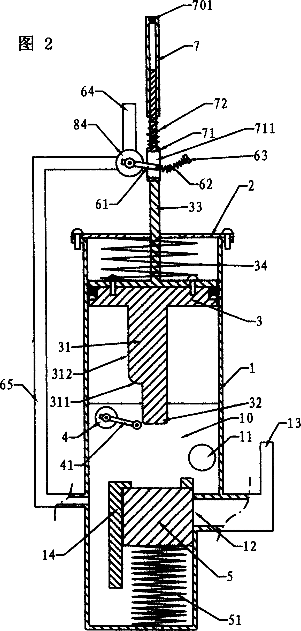
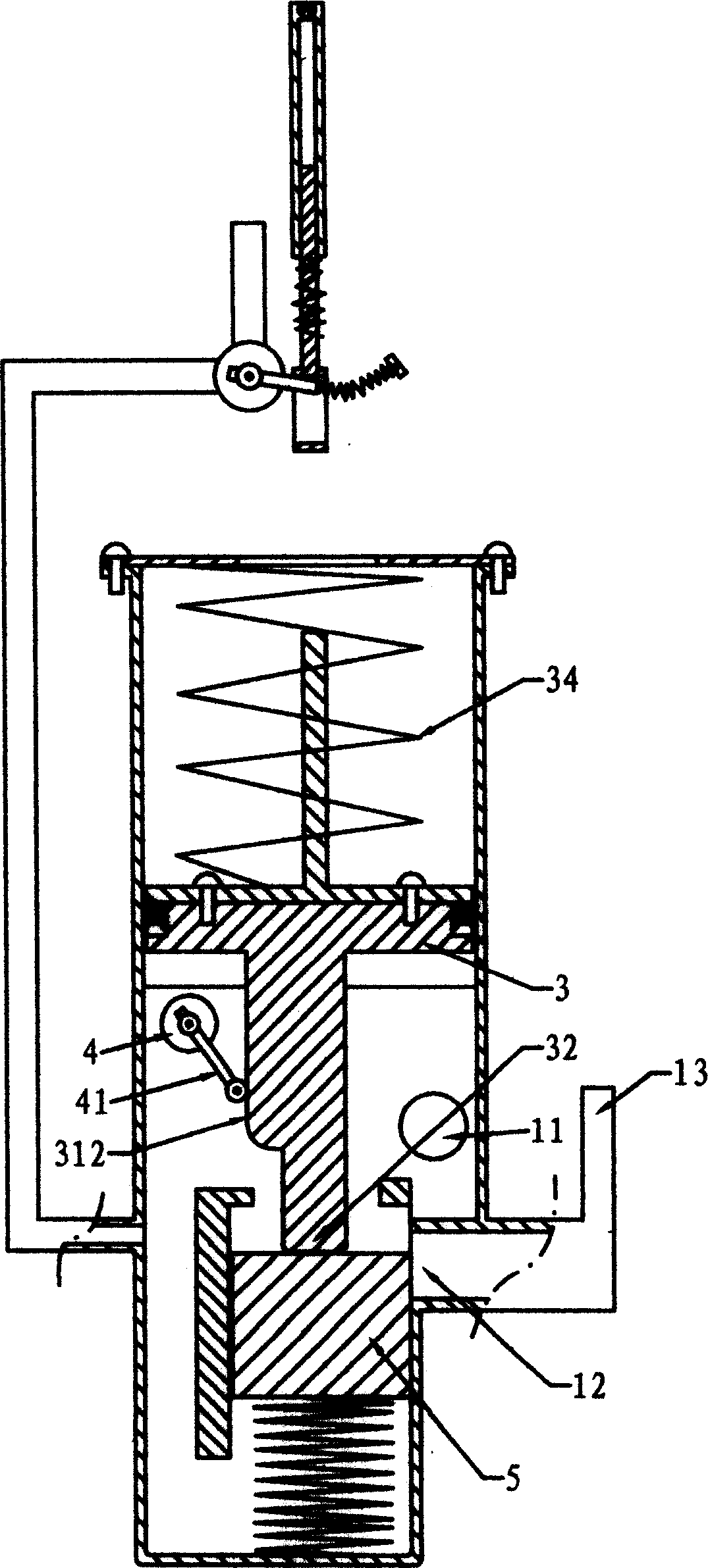
[0051] Embodiment 2. Figure 6 is a schematic diagram of the connection structure and control principle of this embodiment. The difference between Embodiment 2 and Embodiment 1 is that the water mixing valve in Embodiment 1 is changed to a faucet-type water outlet valve 920. Between the water outlet valve 920 and the hot water pipe 99, the one-way valve 910 is used as the control valve, and the joint 9011 between the connecting pipe and the water outlet valve is replaced with a smaller pipe diameter. figure 1 The same, and adopt the water control expansion device with the structure shown in Figure 2, the structure of the stator and moving plate in the switching valve also adopts Figure 4 and Figure 4 respectively Figure 5 The reason why the connection part 9011 adopts a smaller pipe diameter here is to prevent all the water in the pipe from flowing away through the water outlet valve after the water outlet valve 920 is opened, and the hot water in the water tank cannot be eject...

Embodiment 3

[0052] Embodiment three, see Figure 7 , the difference between the third embodiment and the second embodiment is only that the one-way valve in Figure 6 is changed to Figure 7 The normally closed cut-off valve 9100 is used as the control valve, and the stop valve 9100 is controlled by the expansion wall in the water-controlled expansion device. Similarly, the stop valve 9100 can also be integrated in the switching valve together with the overflow valve and the water supply valve. Its working principle is similar to that of the above-mentioned embodiment, and will not be described here.


PUM


Abstract

The mixed water storing water heater with simple structure, use convenience, high safety and long water tank life includes water tank, hot water pipe, water outlet valve, water overflow pipe, tap water pipe and water supply pipe. It features connecting pipe connected to the inlet of the water draining valve, control valve connected between the connecting pipe and the hot water pipe outlet, water controlled expander connected between the connecting pipe and the tap water pipe, normally opened overflow valve connected between the water tank and the overflow pipe, normally slightly opened water intake valve in the tap water passage, and the control of expanding wall in the water controlled expander to the valves. When the water draining valve is opened, the expanding wall controls the water supply valve and the water overflow valve to act instantaneously while the slightly opened water intake valve is slightly opened.

Description

technical field [0001] The invention relates to a water flow control method for a water heater, in particular to a water flow automatic control method for a hybrid water heater. Background technique [0002] In the existing closed water storage water heater water supply system for family or hotel rooms, it includes a water tank, a water supply cold water pipe, a safety valve, a water outlet hot water pipe and a water outlet valve, wherein the water supply cold water pipe connects the water tank with the tap water pipe, and the water outlet hot water pipe Connect the water tank and the water outlet valve. The water tank is filled with hot water. The hot water is heated by heating elements (such as electric heating tubes, electromagnetic field eddy current heating elements - using the principle of electromagnetic cooker, microwave generator - using the principle of microwave oven to heat the water) Heating, heat pump heating system - the reverse work of the refrigeration syste...

Claims


Application Information

Patent Timeline
Patent Type & Authority Applications(China)
IPC IPC(8): F24H9/20
Inventor 麦广海
Owner 麦广海
Why Eureka
Try Eureka