Power tool and miter gauge assembly for table saw

A technology for positioning components and power tools, which is applied in the direction of sawing components, manufacturing tools, positioning devices, etc., and can solve problems such as difficult storage and bulky table saws

Inactive Publication Date: 2006-01-11
BLACK & DECKER INC
View PDF0 Cites 9 Cited by
  • Summary
  • Abstract
  • Description
  • Claims
  • Application Information

AI Technical Summary

Problems solved by technology

This typical table saw is bulky and difficult to store

Method used


Image

  • Power tool and miter gauge assembly for table saw
  • Power tool and miter gauge assembly for table saw
  • Power tool and miter gauge assembly for table saw

Examples


Embodiment Construction

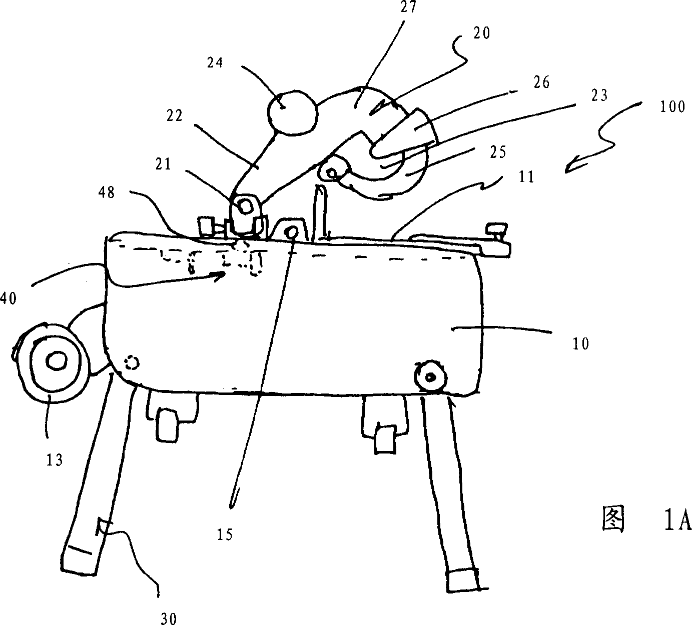
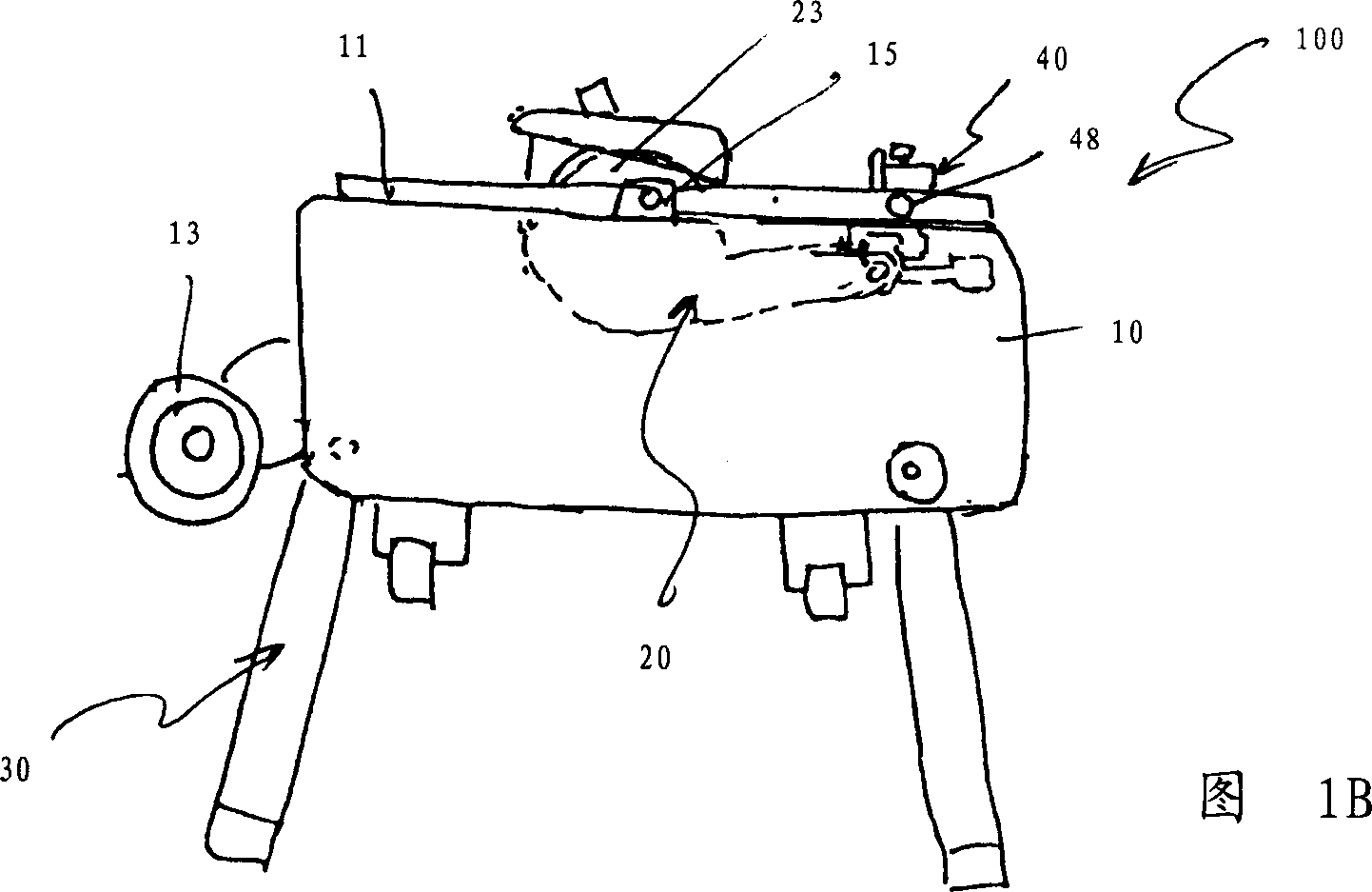
[0009] The invention will now be described with reference to the drawings, wherein like reference numerals refer to like parts. Referring to FIG. 1 , a bench / miter combination saw 100 may include a base assembly 10 , a table assembly 11 supported by the base assembly 10 , and a saw assembly 20 supported by the table assembly 11 . The saw assembly 20 may include a shaft assembly 21 disposed on the table assembly 11 , a pivotable arm 22 pivotably attached to the shaft assembly 21 , and a motor 24 supported by the arm 22 and driving a saw blade 23 . The arm 22 also supports an upper blade guard 27 that covers the upper portion of the saw blade 23 . The lower blade guard 25 is pivotally attached to the upper blade guard 27 . Auxiliary blade guard 26 may be pivotally connected to lower blade guard 25 .

[0010] Preferably, table assembly 11 is pivotally attached to base assembly 10 via joint 15 such that saw assembly 20 can be used as a miter saw when table assembly 11 is in the ...


PUM


Abstract

The present invention provides a power tool with a base assembly and a table supported by the base assembly. The table has a slot. A saw assembly is pivotably supported by the table, and includes a motor, and a blade driven by the motor. A miter gauge assembly is disposable on the slot. The miter gauge assembly has a body, a fence pivotably attached to the body, and a bar pivotably attached to the body, where the bar is disposable in the slot.

Description

technical field [0001] The present invention relates generally to a bevel positioning assembly for a table saw, and more particularly to a bevel positioning assembly for a table / miter combination saw. Background technique [0002] Typical table saws have a bevel positioning assembly to push the workpiece into the saw blade at an oblique angle. Such typical table saws are bulky and difficult to store. Contents of the invention [0003] It is therefore an object of the present invention to provide an easily storable tilt positioning assembly. [0004] In accordance with the present invention, an improved tilt positioning assembly is employed. A power tool having a base assembly; a table supported by the base assembly, the table having a slot; a saw assembly pivotally supported by the table, the saw assembly including a motor and a saw blade driven by the motor, the saw blade being substantially parallel to the slot; and an inclined positioning assembly that can be arrange...

Claims


Application Information

Patent Timeline
Patent Type & Authority Applications(China)
IPC IPC(8): B23D47/04B23Q3/18
CPCB27B5/165B27B27/08Y10T83/7697B27G5/023B27B25/10
Inventor 罗伯特·S·格雷特保罗·M·恩布里罗伯特·库斯米尔斯基阿丹·阿亚拉
Owner BLACK & DECKER INC
Why Eureka
Try Eureka