Resistance and lifting force composite wind pwoer device

A wind power and lift technology, applied in wind turbines, wind turbines at right angles to the wind direction, engines, etc., can solve single problems and achieve the effect of easy starting

Active Publication Date: 2006-01-11
QINGDAO CHENGZHIMEI CREATIVE TECH CO LTD
View PDF0 Cites 10 Cited by
  • Summary
  • Abstract
  • Description
  • Claims
  • Application Information

AI Technical Summary

Benefits of technology

This new design allows for better control over how fast an air turbine rotates when it starts from very slow or stopped downwind conditions. By combining both resistive forces and lifting force on one part, this system can operate without any external devices like a weather vane that could cause damage during high altitude flight operations.

Problems solved by technology

This patented describes different ways for improving the performance of existing wind generators by adding an auxiliary system that increases their lifespan without requiring expensive maintenance. Additionally, there exist various methods used with these systems like adjustable pitch angle wings on top of them (LAPW) or changing the blade's shape from tilted-up to straightened out during operation.

Method used


Image

  • Resistance and lifting force composite wind pwoer device
  • Resistance and lifting force composite wind pwoer device
  • Resistance and lifting force composite wind pwoer device

Examples


Embodiment Construction

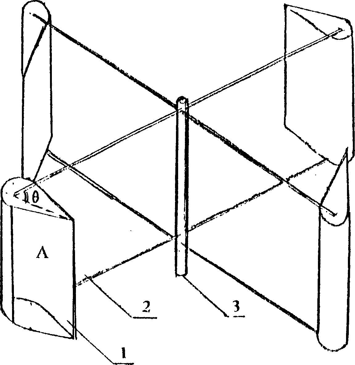
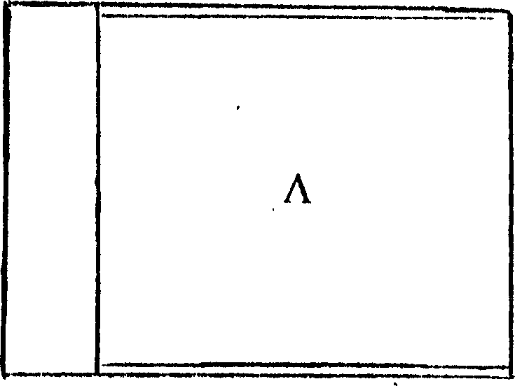
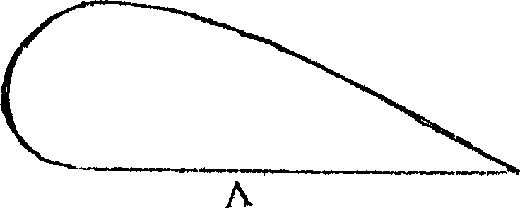
[0013] The airfoil airfoil blade 1 of the wind wheel of the present invention is a special-shaped structure with a concave curved surface made of a thin plate. Rods 2 are uniformly distributed in the axial direction and fixed on the rotating shaft 3 of the wind wheel as the torque output shaft. The included angle θ of pole 2 is 60°-70°. The size of θ angle affects the size and ratio of drag and lift effects. The selection in practical application should be selected according to the local wind conditions. Usually, the annual average wind force is 3 When the level is below 60 days, the θ angle should be larger or close to the upper limit.

[0014] The above-mentioned wind wheel 1 can be an even number of wind blades and is fixed on the wind wheel rotating shaft 3 according to the axial symmetry by means of the connecting rod 2 .

[0015] The above-mentioned thin plate for making the fan blade may be metal or plastic, and the fan blade 1 is an integral structure, which can be ma...


PUM


Abstract

The invention relates to a resistance and lift compound wind power device, in which the wing airfoil-vane of the wind wheel being a special structure with a curved surface is made of sheet. A plurality of air vanes are fixed on the rotation axis of the wind wheel being as the torque output shaft via a link rod. The intersection angle between the chord of each airfoil-vane and the link rod fixing the vanes is an angle of 60~70 degrees. Its character is that the wind vane has the compound action of resistance and lift. When the line speed of the wind vane approaches to the rated wind speed, the backward resistance produced by the wind vane and the quadratic of the relative wind speed of the wind vane forms direct proportion, so that it has automatic speed-limiting function.

Description


Claims


Application Information

Patent Timeline
Owner QINGDAO CHENGZHIMEI CREATIVE TECH CO LTD
Why Eureka
Try Eureka