
A mixing faucet

A faucet and rotary faucet technology, which is applied to indoor sanitary pipeline installations, valve details, multi-way valves, etc., can solve the problem that the rotary handle is not desirable

Inactive Publication Date: 2006-01-18
DAMIXA AS
View PDF0 Cites 3 Cited by
  • Summary
  • Abstract
  • Description
  • Claims
  • Application Information

AI Technical Summary

Problems solved by technology

[0003] But from a design point of view, such a rotary handle is not desirable

Method used


Image

  • A mixing faucet
  • A mixing faucet
  • A mixing faucet

Examples


Embodiment Construction

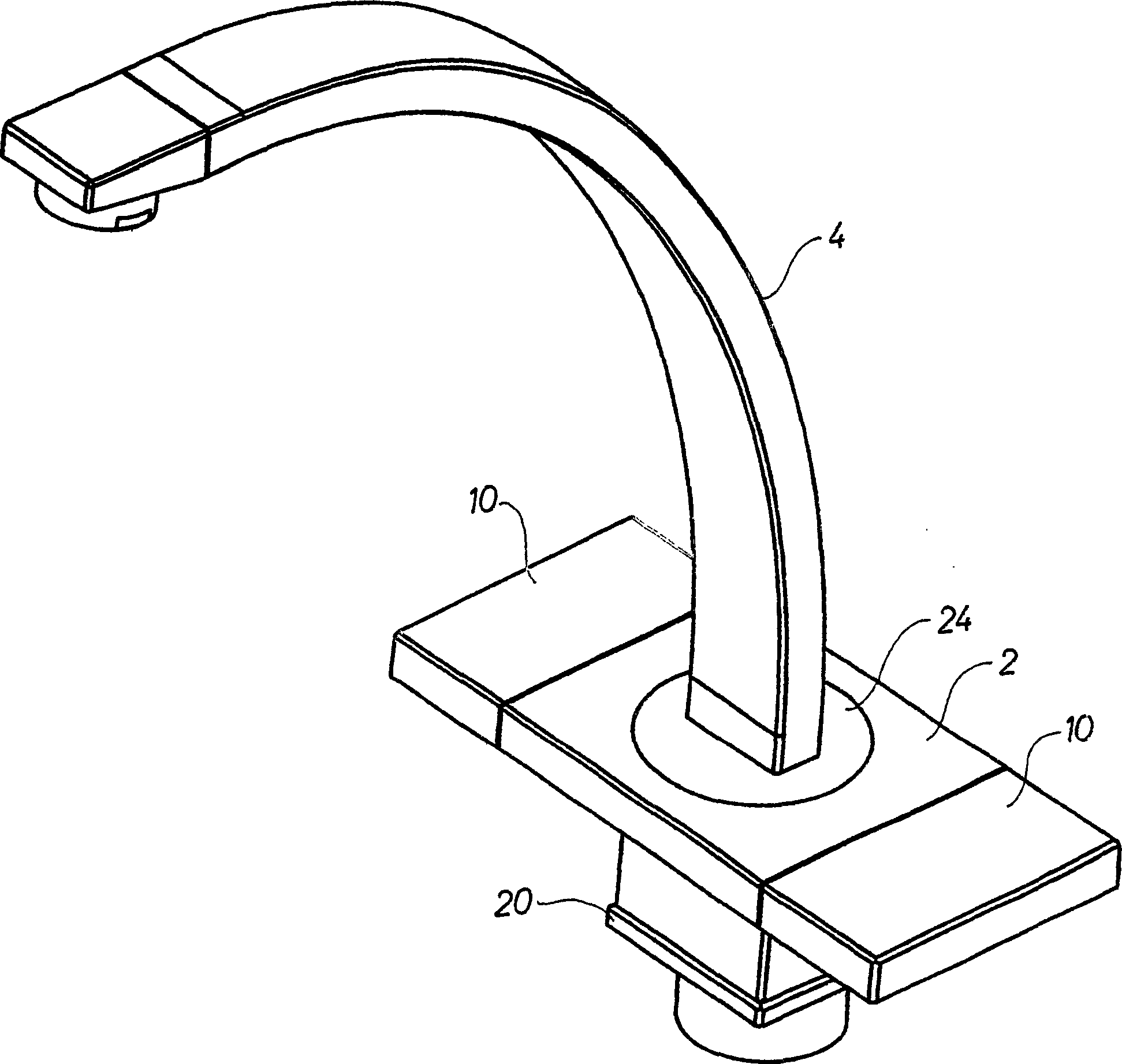
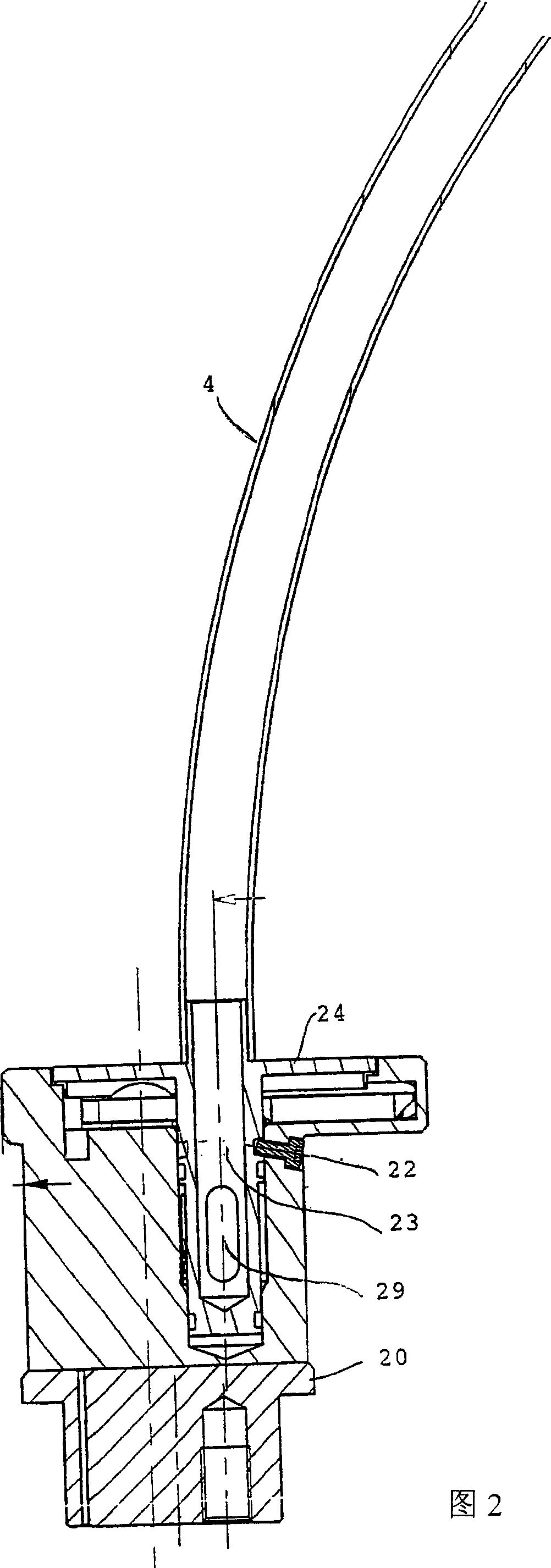
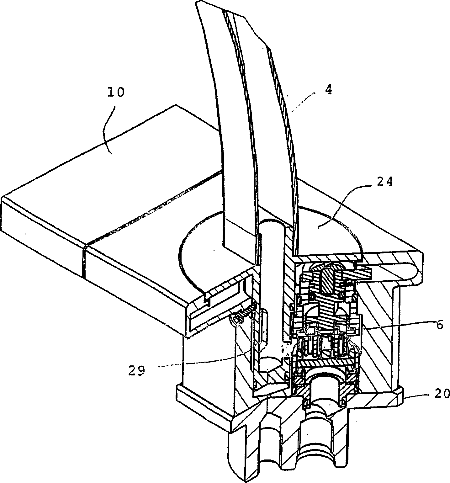
[0013] figure 1 The mixer tap according to the invention shown in , comprises a body part 2 and a swivel tap 4 mounted rotatably on said body part 2 . Such as Figure 4 with Figure 5 As shown in , a rotatable valve stem 6 is installed in the body part 2, the valve stem is used to adjust the water supply of cold water, and the other valve stem is used to adjust the water supply of hot water. In order to obtain figure 1 As shown in the flat appearance, each valve stem 6 is equipped with an extending arm 8, such as Figure 5 shown. The valve stem 6 protrudes from the opening on the side of the body structure 2 and engages with a sliding surface 10 that can slide on one side of the body part 2 and is flat with the upper surface plane of the body part. together. Each sliding surface 10 has an elongated opening, and the protruding portion 12 is fixed to the body part 2 and protrudes into the elongated opening in the sliding surface 10 so that the sliding surface 10 can slide ...


PUM


Abstract

A mixing faucet includes a body part, where a rotatable swivel tap is mounted on said body part, and where a rotatable valve spindle is mounted in said body part for an adjustment of the feeding of cold and hot water, respectively. The rotatable valve spindle is according to the invention equipped with a projecting arm engaging a groove in a slide on the side of the body part. The resulting mixing faucet is much easier to handle than hitherto known.

Description

field of invention [0001] The invention relates to a mixer tap comprising a body part on which a rotatable swivel tap is mounted, a rotatable valve stem for regulating the supply of cold water and a valve for regulating the quantity of hot water A rotatable valve stem for the amount of water supplied is mounted in said body part. Background of the invention [0002] It is common knowledge for mixer taps to include a rotatable handle for turning a rotatable valve stem to adjust the respective volumes of hot and cold water. [0003] However, such a rotary handle is not desirable from a design point of view. Contents of the invention [0004] The object of the present invention is to provide a mixing faucet capable of adjusting the respective water supply volumes of cold and hot water through a sliding surface. [0005] The novel feature of the invention is that in each rotatable valve stem fitted with a projecting arm, said projecting arm engages a sliding surface on the s...

Claims


Application Information

Patent Timeline
Patent Type & Authority Applications(China)
IPC IPC(8): F16K11/20E03C1/04F16K31/58
CPCE03C1/0404E03C1/04F16K31/58F16K11/20Y10T137/87684
Inventor 托本·埃里克森
Owner DAMIXA AS
Learn More