
A workpiece clamping device and machine tool

A technology of clamping device and workpiece, which is applied to workpiece clamping device and machine tool, and the clamping field of workpiece on machine tool, can solve the problems of large clamping twist and unclean working environment, and achieves high clamping precision and high use. The effect of low environment and long service life

Active Publication Date: 2022-07-26
GUANGZHOU HAOZHI ELECTROMECHANICAL
View PDF4 Cites 0 Cited by
  • Summary
  • Abstract
  • Description
  • Claims
  • Application Information

AI Technical Summary

Problems solved by technology

The traditional hydraulic structure requires more space, the hydraulic power system, the working environment is not clean, and the clamping and twisting are large.

Method used


Image

  • A workpiece clamping device and machine tool
  • A workpiece clamping device and machine tool
  • A workpiece clamping device and machine tool

Examples


Embodiment Construction

[0030] This part will describe the specific embodiments of the present invention in detail, and the preferred embodiments of the present invention are shown in the accompanying drawings. Each technical feature and overall technical solution of the invention should not be construed as limiting the protection scope of the invention.

[0031] In the present invention, if there is a description of a direction (up, down, left, right, front and rear), it is only for the convenience of describing the technical solution of the present invention, rather than indicating or implying that the technical features referred to must have specific characteristics Orientation, construction and operation in a particular orientation, and therefore should not be construed as limiting the invention.

[0032] In the present invention, "several" means one or more, "multiple" means two or more, "greater than", "less than", "exceeding", etc. are understood as not including this number; "above", "below" ...


PUM


Abstract

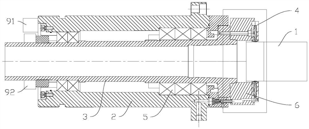
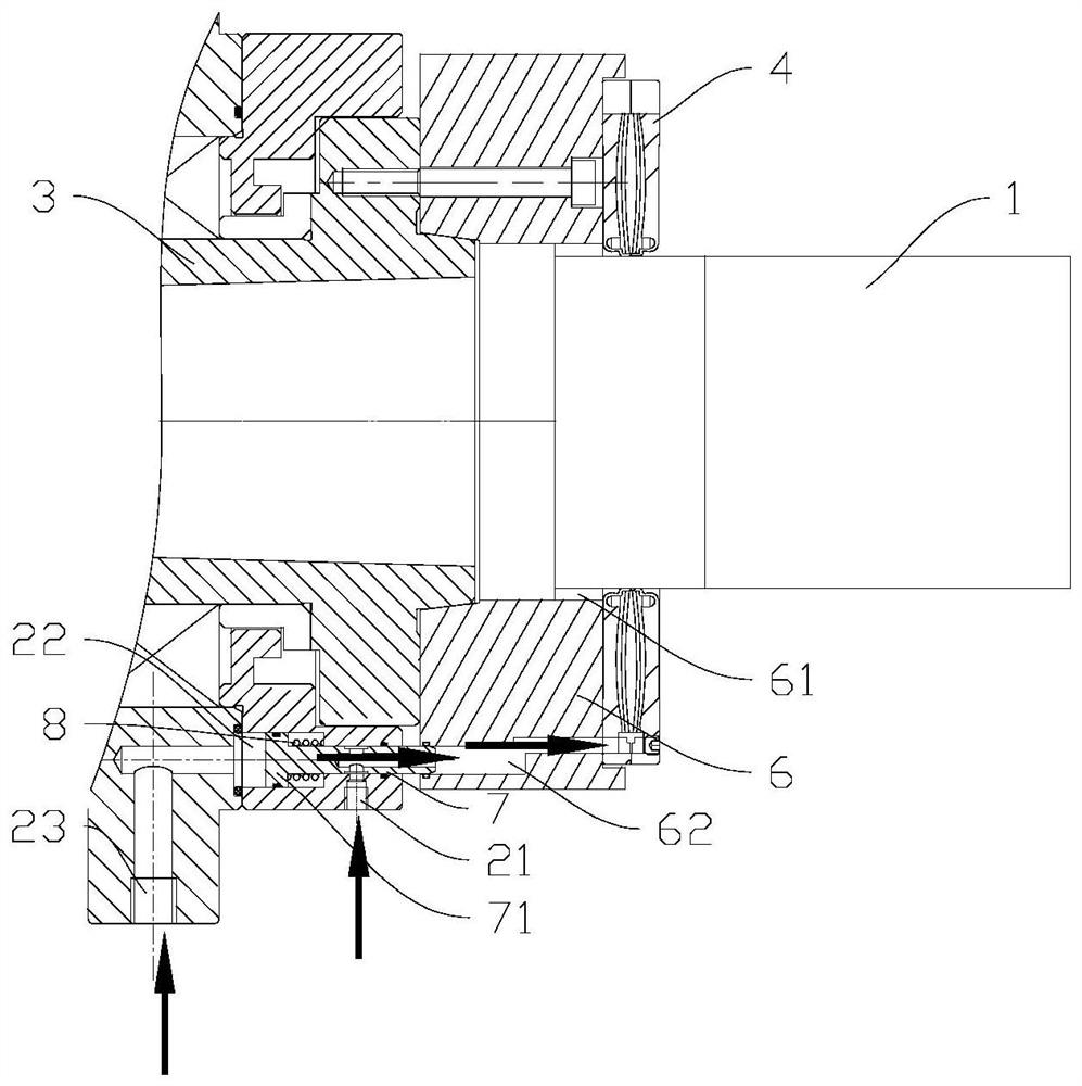
The invention discloses a workpiece clamping device and a machine tool, comprising a box body, a workpiece shaft and a pneumatic brake. The pneumatic brake includes a brake cylinder, which is annular and connected to the workpiece shaft. Inner cavity, the inner cavity has the inner ring cavity wall for locking the workpiece, and the inner ring cavity wall has elastic deformation ability; the spring skin cavity is arranged in the inner cavity, the outer edge of the spring skin cavity is tightly connected with the brake cylinder body, and the spring skin The inner edge of the cavity is in contact with the inner ring cavity wall; among them, after the spring skin cavity is deflated, the spring skin cavity stretches in the radial direction, and exerts a force on the inner ring cavity wall, and the inner ring cavity wall hugs the workpiece; the spring skin cavity is inflated After that, the spring skin cavity expands in the axial direction, and the inner ring cavity wall rebounds and separates from the workpiece. This solution achieves the effect of clamping and loosening by shrinking and expanding in the radial dimension. With this clamping structure, positioning and clamping with high torque and high rigidity can be achieved; at the same time, due to the compact and ingenious structure, the size is smaller than that of the traditional hydraulic piston clamping mechanism.

Description

technical field [0001] The invention is used in the field of machine tools, especially the clamping of workpieces on the machine tools, and particularly relates to a workpiece clamping device and a machine tool. Background technique [0002] In recent years, the machine tool industry has developed rapidly, the competition has become more and more fierce, and the requirements for the processing capacity of machine tools have become higher and higher. Large tightening, high precision and strong stability. The traditional hydraulic structure requires more space, the hydraulic power system, the working environment is not clean, and the clamping twist is large. SUMMARY OF THE INVENTION [0003] The purpose of the present invention is to solve at least one of the technical problems existing in the prior art, and to provide a workpiece clamping device and a machine tool. [0004] The technical scheme adopted by the present invention to solve its technical problems is: [0005]...

Claims


Application Information

Patent Timeline
Patent Type & Authority Patents(China)
IPC IPC(8): B23Q3/00B23Q3/06
CPCB23Q3/00B23Q3/06
Inventor 李文刚张世洋高强汤秀清
Owner GUANGZHOU HAOZHI ELECTROMECHANICAL
Learn More