Drilling and milling machining system with drill bit self-cooling function

A processing system and self-cooling technology, which is applied in metal processing equipment, drilling/drilling equipment, boring machine/drilling machine components, etc., can solve the problems of low integration and achieve improved chip removal speed, high integration, and guaranteed The effect of stability

Active Publication Date: 2019-01-04
东台升华工具有限公司
View PDF5 Cites 7 Cited by
  • Summary
  • Abstract
  • Description
  • Claims
  • Application Information

AI Technical Summary

Problems solved by technology

However, the existing drilling and milling devices only have the basic functions of drilling and milling, and the integration level is low

Method used


Image

  • Drilling and milling machining system with drill bit self-cooling function
  • Drilling and milling machining system with drill bit self-cooling function
  • Drilling and milling machining system with drill bit self-cooling function

Examples


Embodiment 1

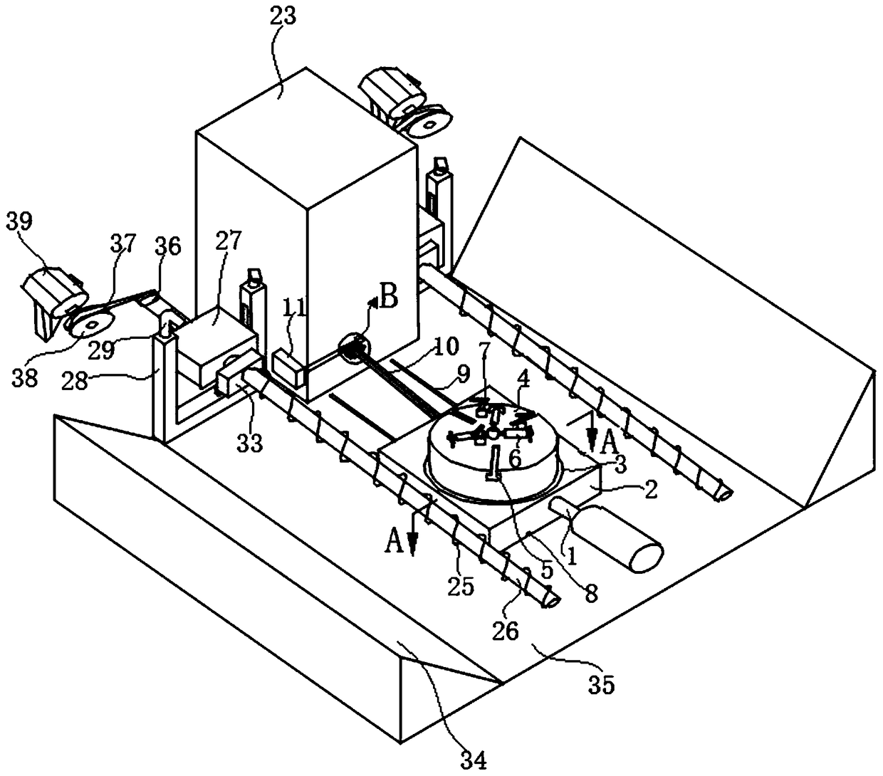
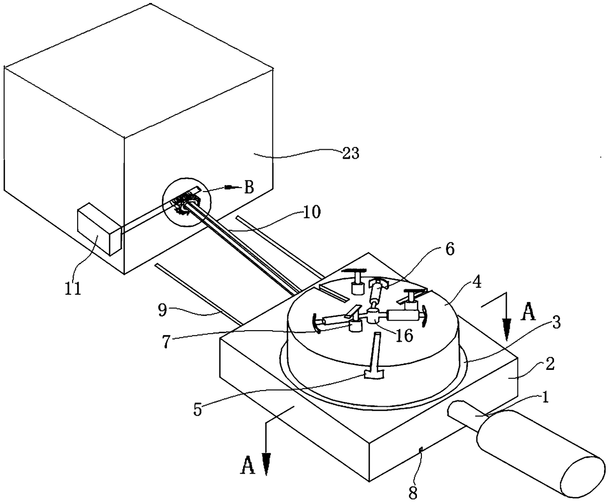
[0065] refer to figure 1 , figure 2 , image 3 , Figure 4 , Figure 5 , Image 6 , Figure 8 as well as Figure 9-13 , the drilling and milling processing system of this embodiment includes: a rotary pressing mechanism 7, a table mechanism, a drilling and milling mechanism, and chip removal mechanisms installed on both sides of the table mechanism, wherein the table mechanism includes: a rotary table 4, a working table Table base 2 and transmission box 23; rotary table 4, rotary table 4 is a cylindrical structure, three telescopic cylinders 6 are installed on the upper surface of rotary table 4, and the central axis of the output shaft of telescopic cylinder 6 passes through the top of rotary table 4 The center of circle of the surface; the end of the output shaft of the telescopic cylinder 6 is equipped with an arc plate 601, and the outer surface of the arc plate 601 is an arc surface; the workbench base 2, the upper surface of the workbench base 2 is provided with a...

Embodiment 2

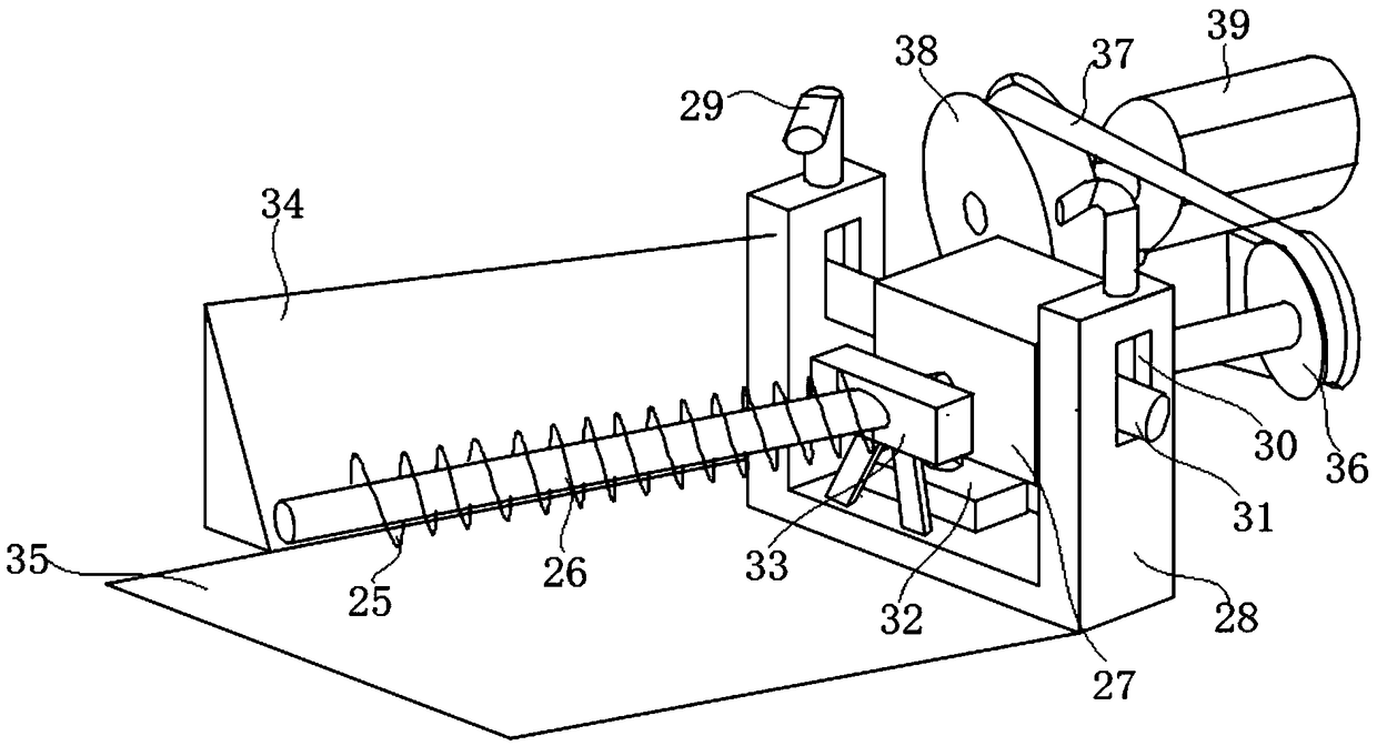
[0075] refer to figure 1 , figure 2 , Image 6 with Figure 7 , the drilling and milling processing system of this embodiment, its structure is basically the same as that of Embodiment 1, further: the upper top surface of the turntable 4 is provided with three chute 5, and the chute 5 is along the radial direction of the upper top surface of the turntable 4 distribution, and the cross section of the chute 5 is an inverted "T" shape, the chute 5 is provided with a sliding piece 18 that can slide in the length direction of the chute 5, the upper end of the sliding piece 18 is equipped with a bearing slider 17, and the bearing slider The side of the block 17 facing the center of the top surface of the rotary platform 4 is a storage step 22, which is stepped and the side of the storage step 22 facing the center of the top surface of the rotary platform 4 is an arc surface; A spiral water pipe groove 4305 is opened on the circumferential surface at the bottom of the spiral chip...

Embodiment 3

[0079] refer to Figure 7 , the drilling and milling processing system of this embodiment, its structure is basically the same as that of Embodiment 2, and further: the side of the bearing slider 17 away from the center of the top surface of the rotary table 4 is a back plate 24, and an arc-shaped baffle plate 20 passes through The first spring 21 is connected on the back plate 24, and the side of the arc-shaped baffle plate 20 facing the center of the top surface of the turntable 4 is an arc surface; the opening at the top of the spiral water pipe groove 4305 is sealed by a sealing strip 4306 made of rubber material .

[0080] In this embodiment, the arc-shaped baffle 20 is connected to the back plate 24 through the first spring 21, and the arc-shaped surface of the side of the arc-shaped baffle 20 facing the center of the top surface of the rotary table 4 is in contact with the rotary support surface to be processed. Fitting, when the slewing bearing to be processed is plac...


PUM


Abstract

The invention discloses a drilling and milling machining system with a drill bit self-cooling function, and belongs to the field of drilling and milling machining devices. The drilling and milling machining system comprises rotary pressing mechanisms, a worktable mechanism, a drilling and milling mechanism and chip removal mechanisms mounted on the two sides of the worktable mechanism correspondingly. The worktable mechanism comprises a rotary table, a plurality of telescopic cylinders are mounted on the upper top face of the rotary table, and the central axes of output shafts of the telescopic cylinders penetrate through the circle center of the upper top face of the rotary table. Arc plates are mounted at the ends of the output shafts of the telescopic cylinders. The drilling and millingmechanism comprises a base which is mounted above a transmission box. A rack is arranged on the base and provided with a milling and drilling machine. The milling and drilling machine comprises a self-cooling drill bit. The multiple rotary pressing mechanisms are mounted on the upper top face of the rotary table and comprise outer cylinder bodies, bearing seats and pressing plates. The drilling and milling machining system has the high integration level.

Description

technical field [0001] The invention relates to the field of drilling and milling processing devices, more specifically, to a drilling and milling processing system with self-cooling of drill bits. Background technique [0002] The drilling and milling device is a machine tool that integrates drilling, milling, boring and grinding. It is used in the processing of small and medium-sized parts, especially in the cutting of non-ferrous metal materials, plastics and nylon. It has the advantages of simple structure and flexible operation. It is widely used in single Components or batches of machinery manufacturing. However, the existing drilling and milling devices only have the basic functions of drilling and milling, and the integration level is low. Contents of the invention [0003] 1. The technical problem to be solved by the invention [0004] The purpose of the present invention is to overcome the deficiency of low integration of existing drilling and milling devices, ...

Claims


Application Information

Patent Timeline
Patent Type & Authority Applications(China)
IPC IPC(8): B23B51/06B23Q1/25B23Q3/06B23Q11/00B23Q11/10
CPCB23B51/06B23Q1/25B23Q3/06B23Q11/0042B23Q11/10
Inventor 李冬
Owner 东台升华工具有限公司
Why Eureka
Try Eureka