Clamp for printing metal products

A product, metal technology, applied in the field of fixtures for metal product printing, can solve problems such as poor protection effect, achieve the effect of avoiding excessive clamping force, simplifying operation steps, and good fixing effect

Inactive Publication Date: 2019-08-23
丁宏建
View PDF8 Cites 6 Cited by
  • Summary
  • Abstract
  • Description
  • Claims
  • Application Information

AI Technical Summary

Problems solved by technology

[0003] A jig for metal product printing proposed by the invention solves the problems of simple structure and poor protection effect of existing printing fixtures

Method used


Image

  • Clamp for printing metal products
  • Clamp for printing metal products
  • Clamp for printing metal products

Examples


Embodiment

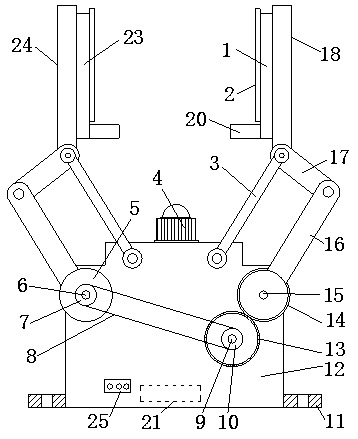
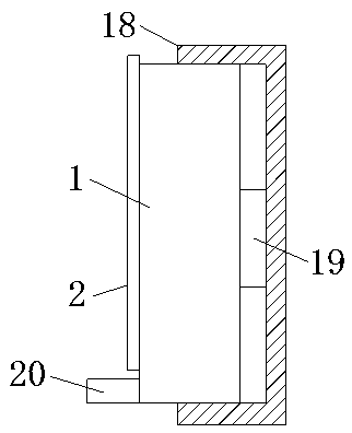
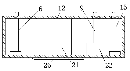
[0022]Embodiment: When in use, the workbench 12 is fixedly installed on the printing equipment through the installation hole on the fixing plate 11, and the product is placed between the first splint 1 and the second splint 23, and the bottom end of the product is in contact with the two stoppers. The support plate 20 touches the limit, and sets a preset value to the controller 21. First, the servo motor 22 is started through the control switch 25. The servo motor 22 works to drive the second rotating shaft 9 to rotate, and the rotating second rotating shaft 9 drives the second chain The wheel 10 and the full gear 13 rotate, the second sprocket 10 drives the first rotating shaft 6 to rotate through the chain 8 and the first sprocket 7, and then drives the rotating disc 5 to rotate, and the rotating full gear 13 drives the incomplete gear 14 to rotate, and then Drive the two first connecting plates 16 to swing reversely at the same time, and then drive the two second connecting ...


PUM


Abstract

The invention discloses a clamp for printing metal products, and relates to the field of machinery. The clamp for printing metal products aims at solving the problems that an existing fixing device for printing is simple in structure and poor in protection effect. According to the technical scheme, the clamp for printing metal products is characterized by comprising a workbench, a controller and aservo motor are fixedly arranged on the inner wall of the workbench, a first rotating shaft and a third rotating shaft are symmetrically and rotationally mounted on the left side and the right side of the inner wall of the workbench through bearings respectively, a second rotating shaft is fixedly connected to a power output shaft of the servo motor, the front end of the first rotating shaft, thefront end of the second rotating shaft and the front end of the third rotating shaft penetrate through the workbench and extend to the outside of the front side of the workbench, a rotating disc is fixedly arranged at the outer end of the first rotating shaft in a sleeving mode, the outer end of the second rotating shaft is fixedly sleeved with a complete gear, and the outer end of the third rotating shaft is fixedly sleeved with an incomplete gear. The clamp is simple and convenient to operate, good in fixing effect, wide in application range, good in protection effect and suitable for popularization and application.

Description

technical field [0001] The invention relates to the mechanical field, in particular to a jig for metal product printing. Background technique [0002] With the rapid development of the printing industry, more and more metal products are printed. During the metal printing process, metal products of different specifications need to be fixed. The existing fixing devices cannot control the clamping force very well. Due to excessive clamping force causing damage to metal products, a fixture for metal product printing is proposed. Contents of the invention [0003] The invention proposes a fixture for metal product printing, which solves the problems of simple structure and poor protection effect of the existing printing fixtures. [0004] In order to achieve the above object, the present invention adopts the following technical solutions: [0005] A jig for printing metal products, including a workbench, a controller and a servo motor are fixedly installed on the inner wall o...

Claims


Application Information

Patent Timeline
Patent Type & Authority Applications(China)
IPC IPC(8): B23Q3/08B41F17/00
CPCB23Q3/08B41F17/00
Inventor 丁宏建
Owner 丁宏建
Why Eureka
Try Eureka