Permanent magnet motor magnetic pole position detection method

A magnetic pole position and detection method technology, which is applied in the direction of control of generators, motor generators, electromechanical transmissions, etc., can solve the problems of large rotor twist and difficult detection of permanent magnet motors, and achieve fast response and detection accurate effect

Pending Publication Date: 2021-03-12
深圳库马克科技有限公司
View PDF3 Cites 0 Cited by
  • Summary
  • Abstract
  • Description
  • Claims
  • Application Information

AI Technical Summary

Problems solved by technology

The conventional method without using sensors is to inject a DC current of known magnitude and direction for a period of time to generate a fixed magnetic field, forcing the rotor to rotate to the position where the two flux linkages are in the same direction, and then start running after stabilization. The method will cause a large twist of the rotor during the positioning process. In some cases, it is forbidden to reverse the motor when starting.
[0004] There is also a method for the initial magnetic pole position of the motor is to inject a high-frequency square wave voltage signal into the permanent magnet motor, and then obtain the magnetic pole position through the relationship between the high-frequency response current in the winding and the magnetic pole position. This method is more obvious for the permanent magnet motor. Effective, but it is difficult to detect accurately for permanent magnet motors whose salient pole effect is not obvious

Method used


Image

  • Permanent magnet motor magnetic pole position detection method
  • Permanent magnet motor magnetic pole position detection method
  • Permanent magnet motor magnetic pole position detection method

Examples


Embodiment Construction

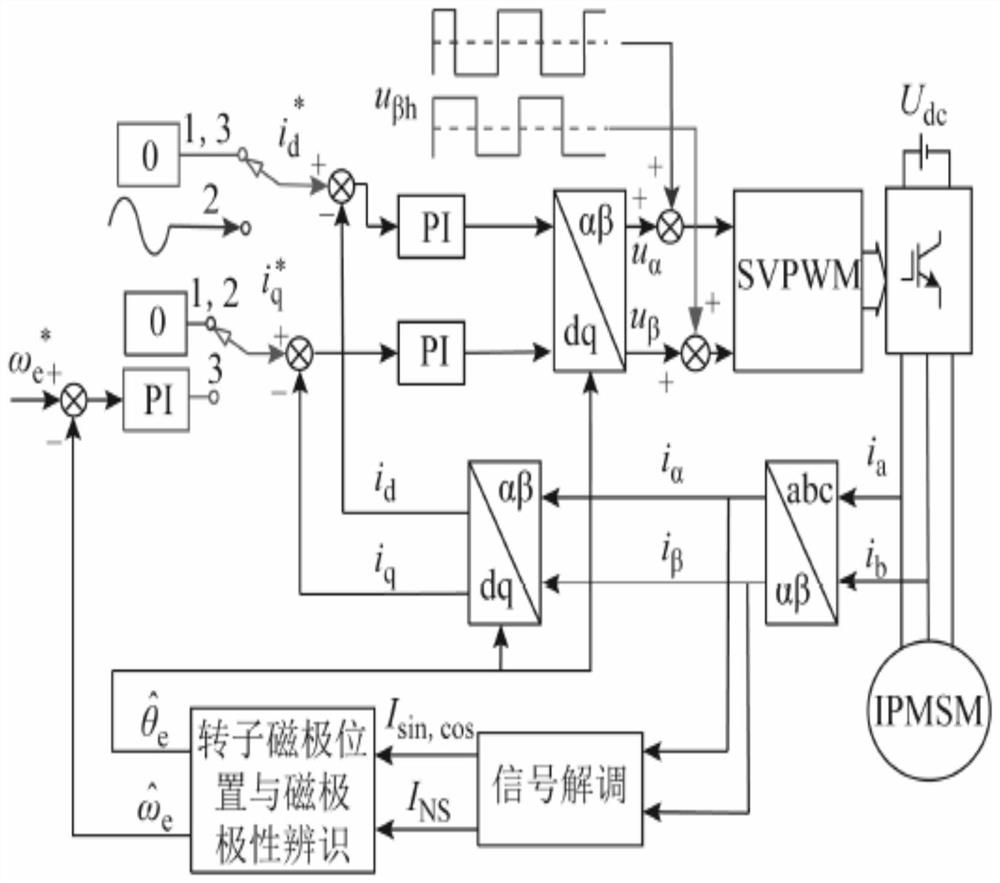
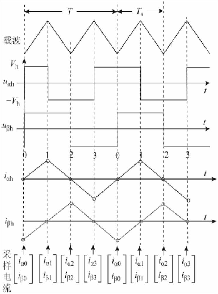
[0036] This method proposes a magnetic pole position identification method based on high frequency quadrature square wave voltage injection. Firstly, by injecting the orthogonal high frequency square wave voltage signal into the stationary coordinate axis, the magnetic pole position is identified by using the high frequency response current signal under the stationary coordinate axis system, and then, while injecting the high frequency orthogonal square wave voltage signal, the The shaft injects a low-frequency sinusoidal current signal, the saturation degree of the motor and the inductance of the AC-D axis will change, causing the high-frequency response current to change, and the magnetic pole polarity can be identified by comparing the amplitude of the high-frequency response current near the positive and negative peaks of the low-frequency sinusoidal current (N pole, S pole).

[0037] The magnetic pole position identification is divided into two stages: the first stage com...


PUM


Abstract

The invention discloses a method for detecting the position of a magnetic pole of a permanent magnet motor. The method comprises the following steps: 101) identifying the position of the magnetic pole: respectively injecting two orthogonal high-frequency square wave voltage signals into an alpha axis and a beta axis, demodulating the high-frequency response current signals on the alpha axis and the beta axis, and identifying the position of a rotor pole; 102) magnetic pole polarity identification: after magnetic pole position identification is completed, keeping high-frequency square wave voltage signal injection unchanged, and injecting a low-frequency sinusoidal current signal of a period into a d axis, so the magnitude of high-frequency response current is changed. The polarity of the magnetic pole is identified by comparing the positive and negative peak values of the low-frequency sinusoidal current signal and the high-frequency response current signal at the positive and negativepeak values. According to the detection method, the rotor is not twisted, the detection is accurate, and the response speed is high.

Description

[technical field] [0001] The invention relates to a permanent magnet motor, in particular to a detection method for the magnetic pole position of the permanent magnet motor. [Background technique] [0002] Permanent magnet motors have been widely used because of their high efficiency, high torque density, low motor operating noise, and excellent control performance. Compared with the traditional electric excitation motor, its working principle is basically the same, the difference is that it abandons the excitation coil, but uses a permanent magnet with high magnetic flux density for excitation, which simplifies the structure of the motor body and further improves the working efficiency of the motor. At the same time, the electronic commutation circuit is used to replace the commutator circuit and brushes, which avoids the shortcomings of commutation sparks and commutation losses; compared with asynchronous motors, permanent magnet motors have no reactive excitation current ...

Claims


Application Information

Patent Timeline
Patent Type & Authority Applications(China)
IPC IPC(8): H02P21/18H02P21/22
CPCH02P21/18H02P21/22
Inventor 童泽文黄洋洋
Owner 深圳库马克科技有限公司
Why Eureka
Try Eureka