Microswitch

A technology of micro switches and switches, which is applied in the direction of electric switches, electrical components, circuits, etc., can solve the problems of cost increase and the influence of the overall size of micro switches, and achieve the effect of avoiding the use of expensive materials

Active Publication Date: 2006-01-25
SCHALTBAU GMBH
View PDF1 Cites 15 Cited by
  • Summary
  • Abstract
  • Description
  • Claims
  • Application Information

AI Technical Summary

Problems solved by technology

Both measures have a negative impact on the overall size of the microswitch
Manufacture of ca

Method used


Image

  • Microswitch
  • Microswitch
  • Microswitch

Examples


Embodiment Construction

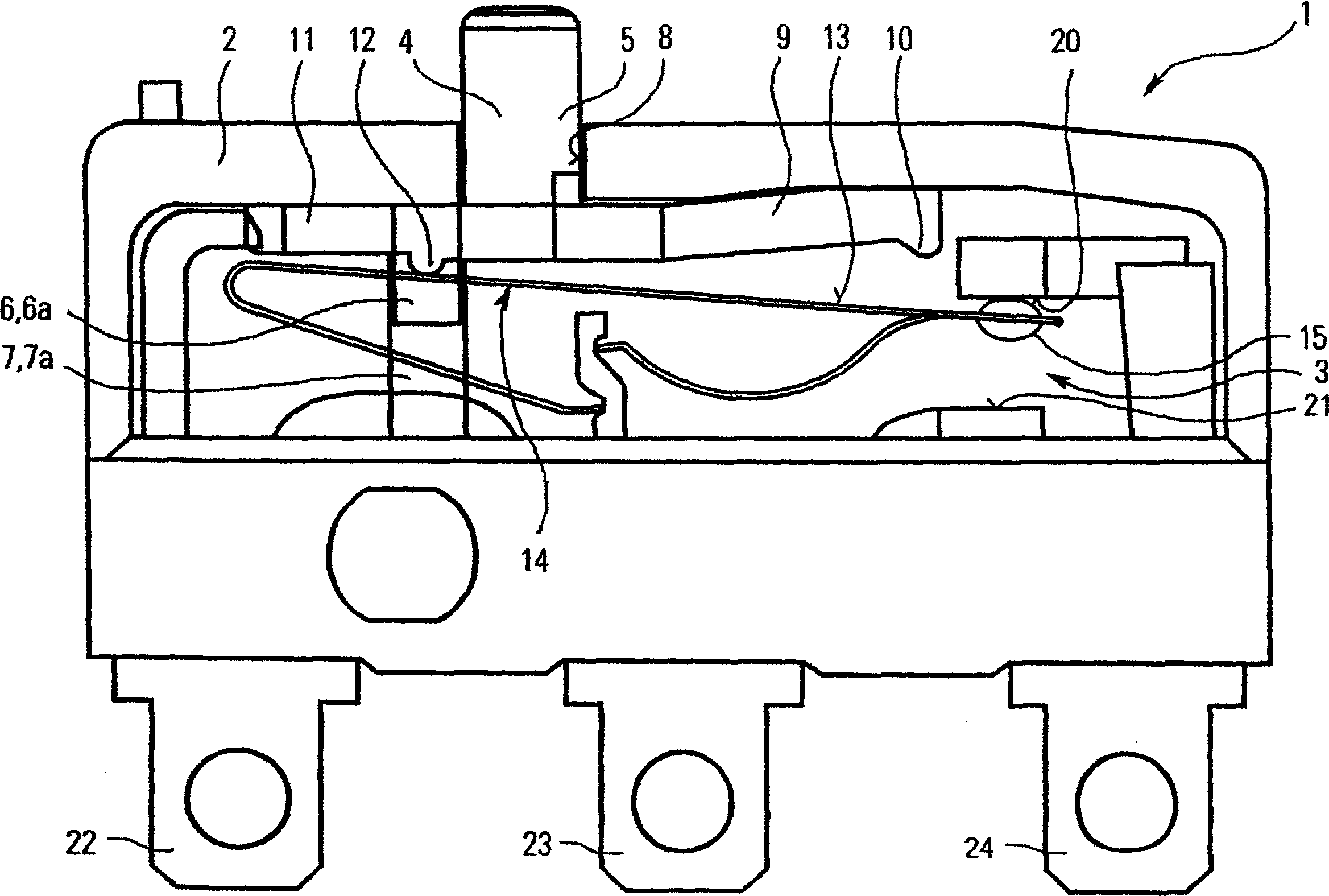
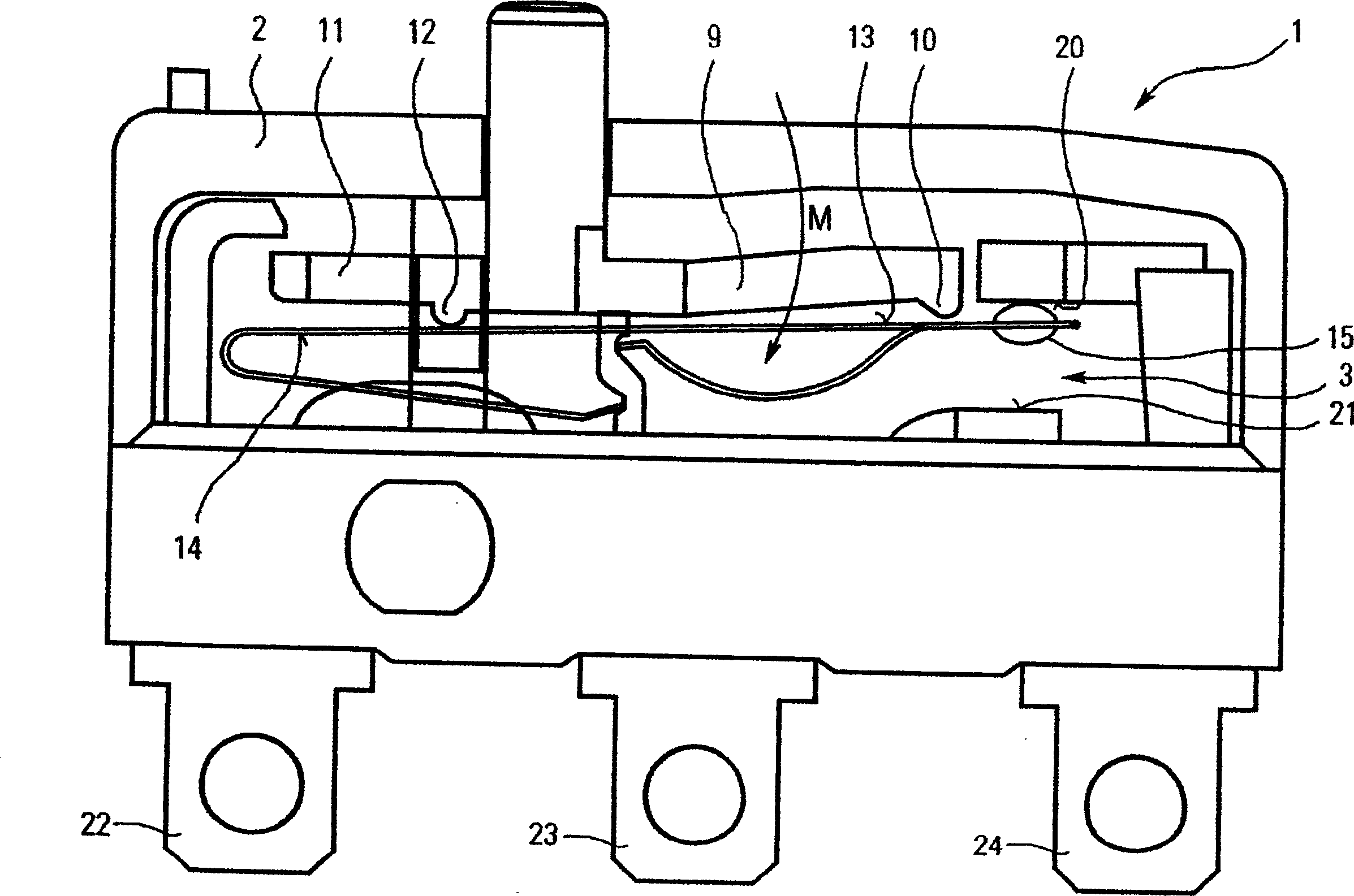
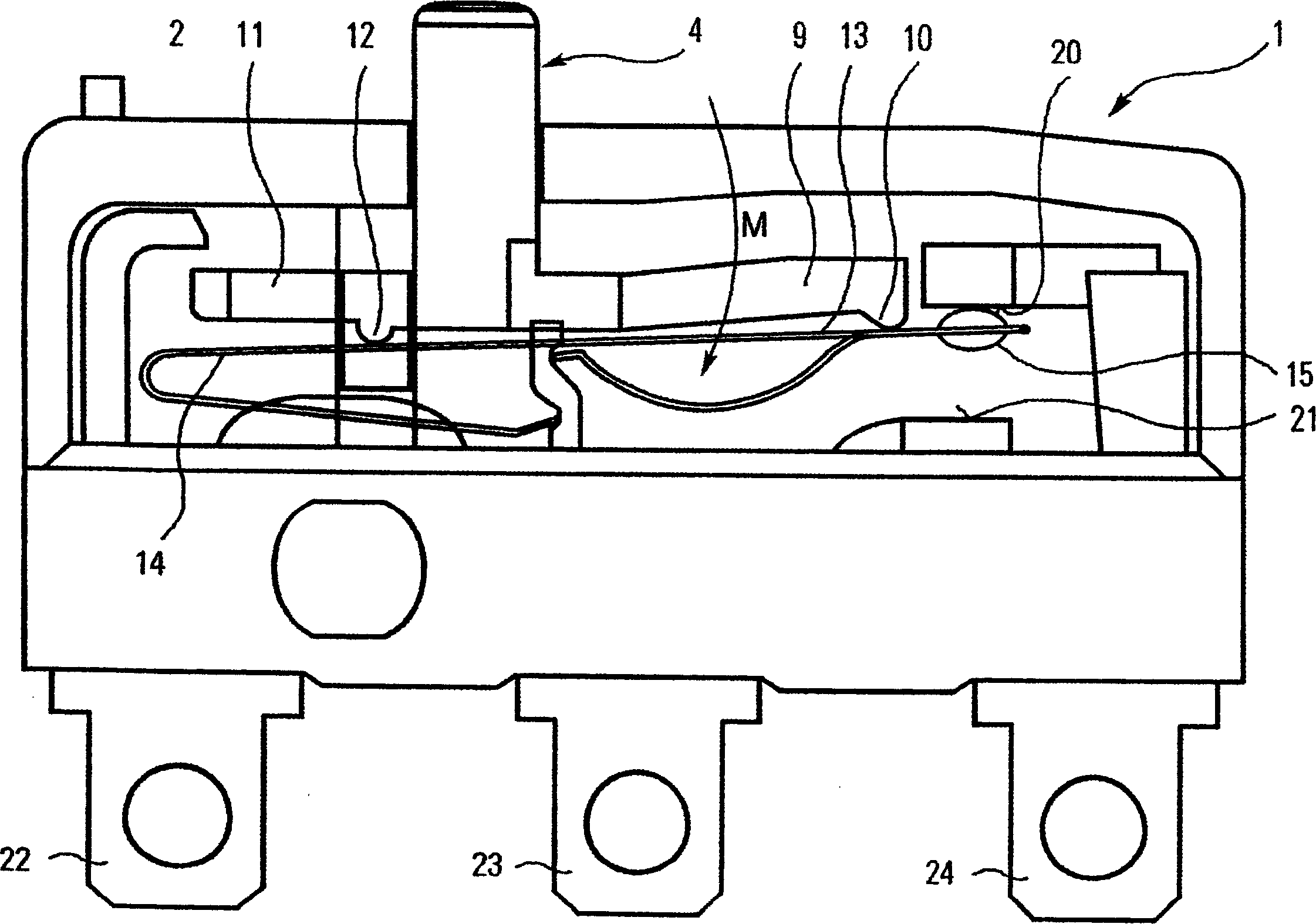
[0016] The accompanying drawing shows a cross-sectional view of a micro switch, which includes a housing 2 and a housing cavity 3 . Mounted on the housing 2 is a switch lever 4 which is provided with two axial guides 5 and 6 which are respectively received in two bearing positions 7 and 8 on the housing 2 . The guide device 6 arranged in the inner cavity of the housing is provided with two guide ribs 6a, which are arranged transversely on the switch lever and engage in two guide grooves 7a provided on the inner wall of the housing at the relevant bearing positions 7. The guide 5 , which is situated opposite the guide 6 , and its associated bearing point 8 has an elliptical cross section. Furthermore, the free end of the switch lever 4 is connected to a limiter 10 via a cantilever. On the side of the switch lever opposite to the cantilever 9 there is arranged an extension which is provided with a support projection 12 . Via the support projection 12, the extension 11 of the s...


PUM


Abstract

The present invention relates to a micro-switch that comprises an outer casing, a switch compression bar that deviate the central arrangement of the casing and extends outwards from the casing, electric contacts that are arranged on the casing and on the side opposite to the switch compression bar, and a contact bridge that can be switched from a first switch position to a second switch position through the switch compression bar and a bistable spring; wherein, the switch compression bar has a cantilever that extends towards one side; the extending end is provided with a limiter that is used for forcing the contact bridge to be opened. In order to improve the micro-switch, further reduces the total size and simultaneously realize the reliable forced opening operation, the design concept of the present invention is to arrange a propping bulge on the side where the switch compression bar and the cantilever are arranged opposite to each other; the bulge acts on a flexible part of the spring that is arranged a certain distance from the switch compression bar, so as to exert a torque (M) on the cantilever of the switch compression bar in the opening direction of the contact bridge, when the switch compression bar is presses down.

Description

technical field [0001] The present invention relates to a micro switch, which comprises a housing, a switch pressure rod arranged away from the center of the housing and protruding outward from the housing, and a plurality of electrical contacts arranged on the housing opposite to the switch pressure rod , and the contact bridge, which can be switched from the first switch position to the second switch position by the switch lever and the bistable spring, wherein the aforementioned switch lever is provided with a cantilever that protrudes to one side, and at its protruding end provides A downholder is provided for the forced opening of the contact bridge. Background technique [0002] An example of such a microswitch is disclosed in patent EP-618603B1 owned by the applicant of the present patent application. In the disclosed microswitch, a bistable spring device is provided, the effect of which is that the switching contacts can be opened quickly so as to reduce the loss of...

Claims


Application Information

Patent Timeline
IPC IPC(8): H01H3/00H01H13/36
CPCH01H13/36H01H3/001
Inventor W·梅尔
Owner SCHALTBAU GMBH
Why Eureka
Try Eureka