Method and device for compensating deflection of cantilever crane and method and device for controlling cantilever crane

A boom and joint angle technology, applied in the field of deflection compensation, can solve the problem that the end of the boom cannot accurately reach the position of the target cloth point

Active Publication Date: 2021-06-25
ZOOMLION HEAVY IND CO LTD
View PDF7 Cites 5 Cited by
  • Summary
  • Abstract
  • Description
  • Claims
  • Application Information

AI Technical Summary

Problems solved by technology

[0002] In automatic cloth, the user only needs to set the position of the cloth point, and needs to obtain the corresponding joint angles through an algorithm. In the prior art, the boom is simplified into a rigid body, and the corresponding joints can be obtained through the rigid inverse kinematics of the boom. However, the actual boom has a large elastic deformation under the influence of gravity, which makes the end of the boom unable to accurately reach the position of the target cloth point

Method used


Image

  • Method and device for compensating deflection of cantilever crane and method and device for controlling cantilever crane
  • Method and device for compensating deflection of cantilever crane and method and device for controlling cantilever crane
  • Method and device for compensating deflection of cantilever crane and method and device for controlling cantilever crane

Examples


Embodiment Construction

[0049] Specific embodiments of the present invention will be described in detail below in conjunction with the accompanying drawings. It should be understood that the specific embodiments described here are only used to illustrate and explain the present invention, and are not intended to limit the present invention.

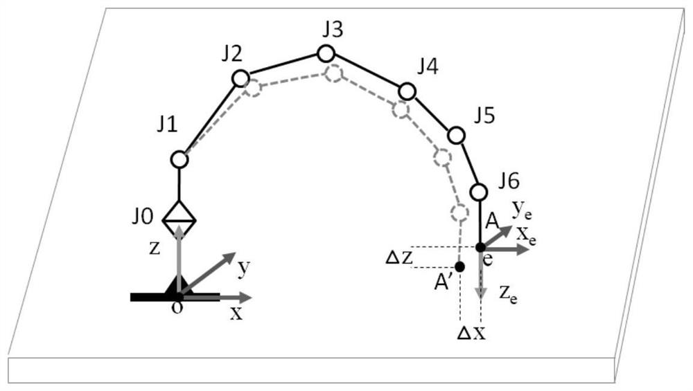
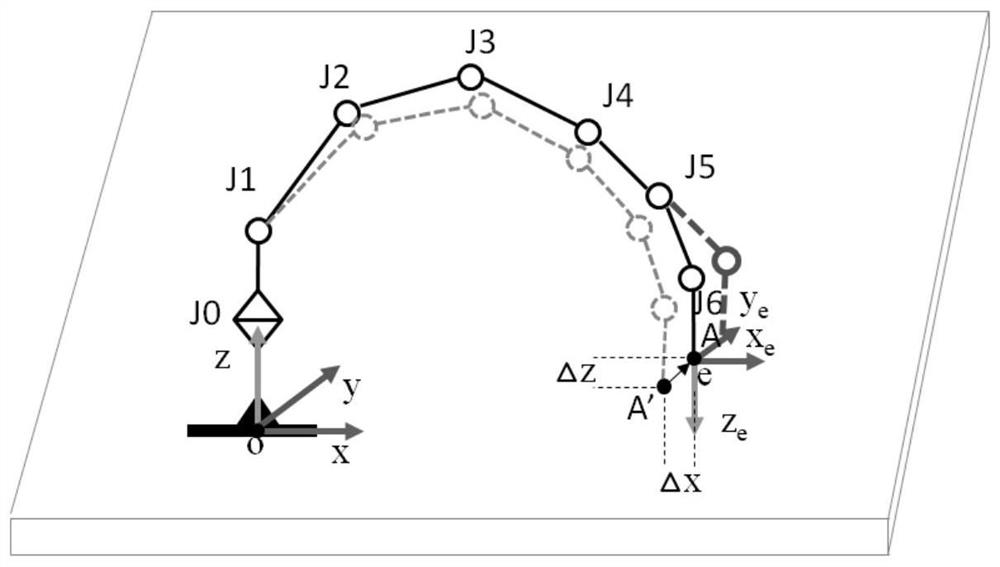
[0050] Taking the 7-DOF jib as an example, its structure is as follows figure 1 As shown, the jib can move 7 joints, J0-J6. Let A be the position where the end of the boom is expected to reach, for example, the desired cloth point, that is, the point e at which the end of the boom is expected to reach figure 1 Point A shown in . If the jib is rigid, a set of joint angles corresponding to the end e of the jib reaching point A can be calculated according to its inverse motion model. Assume that the arm frame configuration corresponding to the set of joint angles obtained is as follows: figure 1 Shown by the black solid line. Due to the elastic deformation of ...


PUM


Abstract

The invention relates to the field of deflection compensation, and discloses a method and a device for compensating the deflection of a cantilever crane and a method and a device for controlling the cantilever crane. The method for compensating the deflection of the cantilever crane comprises the following steps that a joint angle group of the cantilever crane is determined if the tail end of the cantilever crane reaches a preset target position under the condition that the cantilever crane is regarded as a rigid body, wherein the joint angle group comprises joint angles of all joints of the cantilever crane, the actual position where the joint angle group enables the tail end to reach is determined, the deviation between the preset target position and the actual position is determined; and under the condition that the deviation does not meet the preset condition, the joint angle group is adjusted, and under the condition that the deviation determined according to the adjusted joint angle group does not meet the preset condition, the joint angle group continues to be adjusted till the deviation meets the preset condition. Therefore, the tail end of the cantilever crane can accurately reach the preset target position.

Description

technical field [0001] The invention relates to the field of deflection compensation, in particular to a method and device for compensating the deflection of a boom and a method and device for controlling the boom. Background technique [0002] In the automatic cloth, the user only needs to set the position of the cloth point, and needs to obtain the corresponding joint angles through the algorithm. In the prior art, the boom is simplified into a rigid body, and the corresponding joints can be obtained through the rigid inverse kinematics of the boom. However, the actual boom has a large elastic deformation under the influence of gravity, which makes the end of the boom unable to accurately reach the position of the target cloth point. Contents of the invention [0003] It is an object of the present invention to provide a method and a device for compensating the deflection of a jib and a method and a device for controlling a jib, which solve or at least partly solve the a...

Claims


Application Information

Patent Timeline
Patent Type & Authority Applications(China)
IPC IPC(8): B25J18/00B25J17/00B25J17/02
CPCB25J18/00B25J17/00B25J17/02
Inventor 廖亚军付玲皮皓杰唐律李明军
Owner ZOOMLION HEAVY IND CO LTD
Why Eureka
Try Eureka